How 6502 Overflow Works

6502 Overflow Circuit

The 6502 was a ubiquitous microprocessor back in the 80s, powering devices such as the Apple II and the Nintendo Entertainment System. [Ken] took an in depth look at a small part of the processor: the overflow circuit.

In order to do signed calculations, a microprocessor’s arithmetic logic unit (ALU) needs to be able to calculate when an overflow occurs. This happens when two numbers are added that cannot fit in a single byte. The result of a calculation will be incorrect, so the processor must inform the program that an overflow has occurred. This is done by setting an overflow flag.

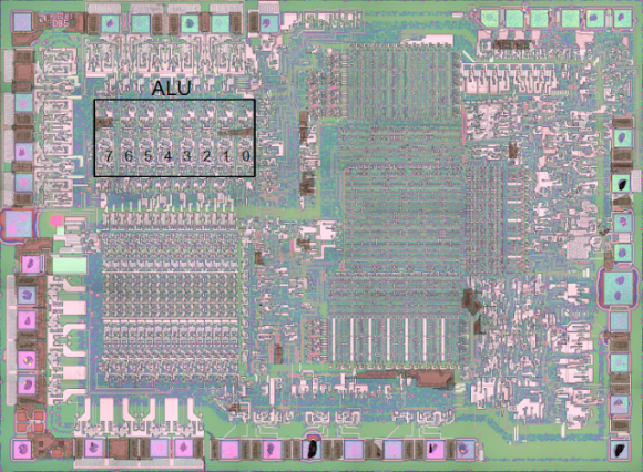
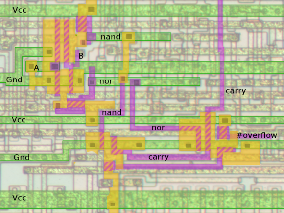
[Ken] uses this example to first explain how the overflow circuit works in logic. He then looks at the gates and a transistor implementation of the logic. Finally, he walks us through the circuit on the actual 6502 die, showing how the circuit is constructed in silicon.

This is a great example to learn a bit more about how ALUs work and how integrated circuits get built.

Breadboarding A 4-bit ALU

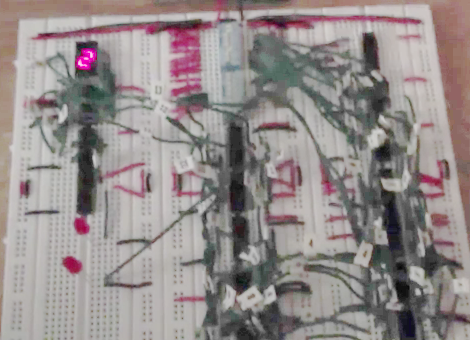
[TGTTGIT] recently took the plunge and decided to build his own computer using logic chips. He just completed a 4-bit ALU which can compute 18 functions. It took a long time to get the wiring right, but in true geek fashion his build was accompanied by an alternating Chapelle’s Show and Star Trek: TNG marathon playing in the background.

This project is the stepping stone for a larger 16-bit version. The experience of wiring up just this much of it has convinced him that an FPGA is the only way to go for the future of the build. But since he had already ordered the chips it was decided that the only thing to do was to see this much through. He used the truth table from The Elements of Computing Systems for the design and posted several times about the project before arriving at this stopping point so you may be interested in clicking through the other post on his blog. There’s also a lot of other TTL computer projects around here worth checking into.

Continue reading “Breadboarding A 4-bit ALU”

The TIM-8 Is The Smallest 8-bit Relay Computer Ever

Who wouldn’t want to build a computer out of relays? We do, but we’ve got too many projects on our plate already. It looks like [rory] has his priorities in order because his build is one of the most amazing we’ve ever seen.

We’ve seen [Harry Porter]’s amazing relay computer and we’re familiar with [Konrad Zuse]’s WWII era endeavours. Relay computers aren’t exactly uncommon, but [rory] built the TIM-8, that may be the smallest 8-bit relay computer ever. The total relay count in the TIM-8 is 152 compared to [Harry Porter]’s 415 relays. This isn’t a fair comparison because [Harry]’s uses 4-pole relays, while the TIM-8 uses 1-pole relays, making the [rory]’s project 8 times smaller than [Harry]’s.

There are a couple of neat features that makes the TIM-8 really exceptional. Programs for the TIM-8 are written in a text editor on [rory]’s desktop,  then compiled and printed onto receipt paper. The TIM-8 has a few phototransistors to read the bands of white and black printed on the paper. [rory] has come a long way from a three bit adder made with relays and light bulbs.

Check out a ton of videos after the break. There’s a few demos of programs running off of receipt tape, calculating the Fibonacci sequence, and playing ‘Mary Had a Little Lamb’ on the relay sound card. Thanks to [J. Peterson] for sending this one in.

Continue reading “The TIM-8 Is The Smallest 8-bit Relay Computer Ever”