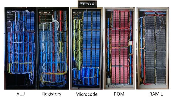
It’s one thing to create your own relay-based computer; that’s already impressive enough, but what really makes [DiPDoT]’s design special– at least after this latest video— is swapping the SRAM he had been using for historically-plausible capacitor-based memory.
A relay-based computer is really a 1940s type of design. There are various memory types that would have been available in those days, but suitable CRTs for Williams Tues are hard to come by these days, mercury delay lines have the obvious toxicity issue, and core rope memory requires granny-level threading skills. That leaves mechanical or electromechanical memory like [Konrad Zuse] used in the 30s, or capacitors. he chose to make his memory with capacitors.
It’s pretty obvious when you think about it that you can use a capacitor as memory: charged/discharged lets each capacitor store one bit. Charge is 1, discharged is 0. Of course to read the capacitor it must be discharged (if charged) but most early memory has that same read-means-erase pattern. More annoying is that you can’t overwrite a 1 with a 0– a separate ‘clear’ circuit is needed to empty the capacitor. Since his relay computer was using SRAM, it wasn’t set up to do this clear operation.
He demonstrates an auto-clearing memory circuit on breadboard, using 3 relays and a capacitor, so the existing relay computer architecture doesn’t need to change. Addressing is a bit of a cheat, in terms of 1940s tech, as he’s using modern diodes– though of course, tube diodes or point-contact diodes could conceivably pressed into service if one was playing purist. He’s also using LEDs to avoid the voltage draw and power requirements of incandescent indicator lamps. Call it a hack.
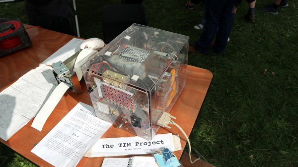
He demonstrates his circuit on breadboard– first with a 4-bit word, and then scaled up to 16-bit, before going all way to a massive 8-bytes hooked into the backplane of his Altair-esque relay computer. If you watch nothing else, jump fifteen minutes in to have the rare pleasure of watching a program being input via front panel with a complete explanation. If you have a few extra seconds, stay for the satisfyingly clicky run of the loop. The bonus 8-byte program [DiPDoT] runs at the end of the video is pure AMSR, too.
Yeah, it’s not going to solve the rampocalypse, any more than the initial build of this computer helped with GPU prices. That’s not the point. The point is clack clack clack clack clack, and if that doesn’t appeal, we don’t know what to tell you.
Continue reading “Capacitor Memory Makes Homebrew Relay Computer Historically Plausible”