Gaming Scoreboard And Storage Box In One

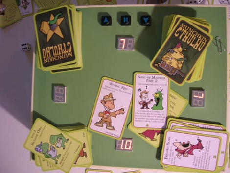
This game storage box will also keep score for you. [Marcus] built it for playing the card game Munkin, but some clever programming could adapt it for most needs. The hardware is built around an ATtiny2313 to do the thinking, and a MAX7219 to drive the 7-segment displays. Each player has their own two-digit score readout, which is perfect for this game which only tracks scores from -9 up to 10.

In the video after the break you can see [Marcus’] explanation of the user interface. One player acts as scorekeeper for the game. That person uses three buttons to adjust the score as necessary, and to move the current player marker, expressed as a decimal point on one of the displays. Pressing all three keys will put the unit into programming mode. This lets you select the number of players and at which position they are sitting, as well as make adjustments to the score if necessary.


Continue reading “Gaming Scoreboard And Storage Box In One”

Roland 808 Synced To MIDI

Reading this week’s ATtiny-themed builds, [Thomas] was reminded one of his coolest builds. His midi808 project used an ATtiny2313 to sync a vintage Roland 808 drum machine to his Logic workstation.

Even though MIDI had been around for a few years when 808s were being made, the CPU in the 808 isn’t exactly up to the task of handling MIDI. Instead, the 808 used an interface known as DIN Sync that was designed to keep 808s, 707s, and 303s in time with each other. MIDI to DIN Sync boxes do did exist, but even the auxiliary equipment to use an 808 is getting hard to find.

The build takes a MIDI signal and passes it through an opto-isolator per the MIDI spec. The microcontroller reads the MIDI signal and passes it out through the DIN Sync port. The DIN Sync protocol is only 24 pulses per quarter note output with TTL voltages, and the project code is easy enough to follow. It’s a nice build for one of the greatest drum machines ever made. Listen to a track [Thomas] made with his new setup after the break.

Continue reading “Roland 808 Synced To MIDI”

ATtiny Hacks: 2313 Driving A 4x4x4 LED Cube

ATtiny Hacks Theme Banner

[Kirill] wrote in to share his ATtiny hack, a 4x4x LED cube. The 64 LED display is a great choice to fully utilize the hardware he chose. It’s multiplexed by level. Each of the four levels are wired with common cathodes, switched by a 2N3904 transistor. The anodes are driven by two 595 shift registers, providing a total of 16 addressable pins which matches the 4×4 grid perfectly. All said and done it only takes seven of the ATtiny2313’s pins to drive the display. This is one pin more than the chip’s smaller cousins like the ATtiny85 can provide. But, this chip does include a UART which means the project could potentially be modified to receive animation instructions from a computer or other device.

You may have noticed the USB port in the image above. This is serving as a source for regulated power in lieu of having its own voltage regulation hardware and is not used for data at all. Check out the animations that [Kirill] uses on the display by watching the video after the break. You’ll find a link to the source code there as well.

Continue reading “ATtiny Hacks: 2313 Driving A 4x4x4 LED Cube”

AVR HVSP On A Tiny Breadboard

AVR chips are convenient because you can program them in circuit at their operating voltage. That is, unless you screw up the fuse settings and they’ll no longer listen to an In System Programmer. If you find yourself facing this problem, just build this circuit on a breadboard and ‘unbrick’ by holding down the button.

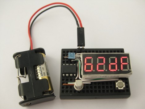
The circuit seen above is a High Voltage Serial Programmer. This is one of two high voltage protocols used by AVR chips; HVSP is for chips that don’t have enough pins to use High Voltage Parallel Programming. This rendition uses a 12V power source, which is the level necessary for the high voltage method. A 7805 linear regulator joins the mix to provide operational voltage, along with one transistor, an ATtiny2313 to control the circuit, a four-digit 7-segment display for feedback, and one button for control.

Watch the video after the break to see an ATtiny13 programmed to disable the reset pin using a breadboarded programmer. That chip is then easily rescued, having been automatically recognized by using its device signature.

Continue reading “AVR HVSP On A Tiny Breadboard”

Designing A Controllable RGB LED Driver Board

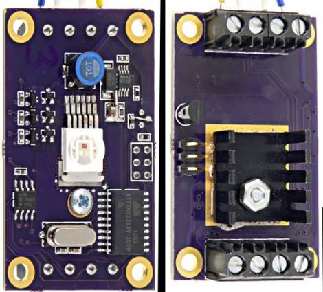
[Paul] wrote in to tell us about this LED driver board he’s been working on with a few friends. The collaborators had been unhappy with the Lumens per Watt ratings (or lack of a rating) on low powered LEDs and set out to find a better solution. They picked up the beefy ASMT-MT00 which houses all three diodes in one package, with all the pins on one side of the surface mount package, a heat dissipating tab on the other side, and pushed 30 Lumens per Watt. With that in hand they set out to design a host board for the blindingly bright light.

The board includes a heat sink on the underside. To drive the LEDs [Paul] sourced an LM3407 constant current driver. The manufacture recommends using one of these chips for each of the colors in the LED package. [Paul] built a circuit that allows him to route power around each LED, making the system work with just one low-side driver. From there, an ATtiny2313 provides addressable control via the RS485 protocol. Screw terminals on either end of the PCB allow this to be chained along with other modules, and they’ve already worked out a basic PureData program that will be able to address multiple boards once they finish manufacturing them.

MIDI Input For The Kaossilator

This isn’t strictly a MIDI input hack; [Furrtek] pulled off an alternate input hack for the Kaossilator that he’s currently using with a MIDI connection. In its unhacked form the Kaossilator is a small touchpad-based sound manipulation tool. [Furrtek] sniffed out how the touchpad data is read and used on the little device. He then purposed an ATtiny2313 as the core of a circuit that spoofs those signals. The microcontroller now listens for incoming MIDI data, looks up the proper signal translations in a table, then outputs them to the Kaossilator.

In the video after the break you can see that it works perfectly, with no lag or noticeable problems. As we alluded to at the top, there could be so much more done with this. Since the ATtiny2313 is merely translating MIDI into touchpad signals, the input could be anything. The first thing that comes to mind is a dance floor that changes the music based on how many people are out there tearing it up. Continue reading “MIDI Input For The Kaossilator”

Surprisingly Simple Magnetic Card Spoofer

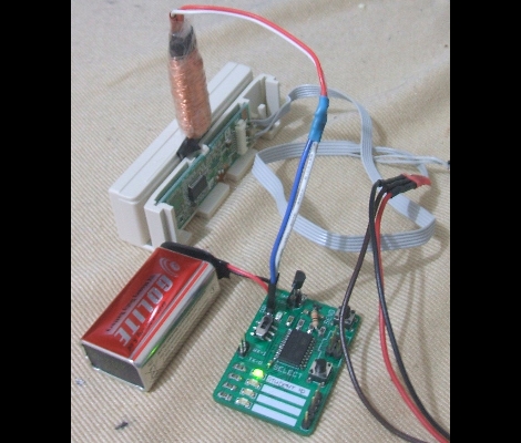
[Craig’s] magnetic card spoofer is both simple and brilliant. There are two parts to spoofing these cards and he took care of both of them. The first part is getting the actual card data. He designed the spoofer board with a header that connects to a card reader for doing this. The second part is the spoofing itself, which is done with an electromagnet. As with past spoofers, he wrapped a shim with enamel-coated magnet wire. An old knife blade was picked for its thickness and ferromagnetism.  This magnet is driven by an ATtiny2313 which stores the data, and is protected by a transistor driving the coil. There were a few design flaws in his board, but [Craig] was able to get the same track data out of the spoof as the original card despite the LED being used as a protection diode and an ‘aftermarket’ resistor on the transistor base.