Apartment Entry Morse-code Lock

[Bozar88] lives in an apartment building that has a buzzer at the front security door. Guests find your name on the panel next to that door, and press a button to ring the phone just inside the entry of each apartment unit. He decided to extend the built-in capabilities by adding a morse-code entry password which unlocks the security entrance automatically (translated).

He designed a circuit and etched his own board which fits nicely inside of the wall-mounted phone. It uses an ATtiny2313 to implement the coding functions. The device attaches to the intercom line in order to detect incoming button presses from the entry panel. There’s some protection here to keep the signal at or below 5V. The output is two-fold. The microcontroller can drive the microphone line using a transistor, which gives the user audio feedback when the code is entered. To unlock the door an opt-isolated triac (all in one package) makes the connection to actuate the electronic strike on the entry door.

The video after the break is not in English, but it’s still quite easy to understand what is being demonstrated.

Continue reading “Apartment Entry Morse-code Lock”

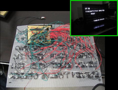
Interesting Substrate Used To Position LEDs Of This Word Clock

[Ivan] decided to build a Word Clock as holiday gift for his parents. He pulled it off, but as you can see above, it meant a lot of point-to-point soldering. One small piece of proto-board is used to host the power supply and a few integrated circuits, with the rest of the device mounted on an interesting choice of material.

The substrate that holds the LED array for the display is a plastic mesh. You’ll find the stuff in any craft store, it’s meant for use in yarn work. It comes rated in several different sizes designated by holes-per-linear-inch. This is fantastic because it makes precision spacing a snap. The face plate itself looks great, especially when you consider that all of the letters were cut out from a piece of black foam board by hand. This bezel was then put in a picture frame, with a bit of tissue paper as a diffuser.

They tell us that the code was written in assembly for an ATtiny2313 microcontroller. It uses a DS1305 RTC chip to keep time and you might be interested to see how the communication protocol was implemented in assembly. The project is based on [Doug’s] Word Clock which we covered in this links post.

BB313 Breadboard Platform Makes ATtiny Prototyping Painless

Johngineer's BB313

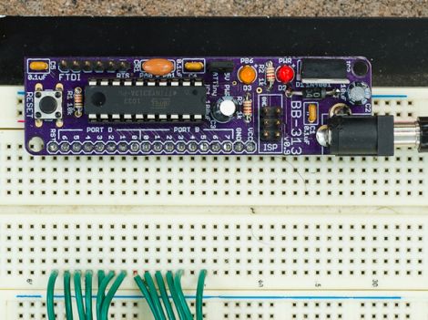
[John De Cristofaro aka Johngineer] uses various ATmega microcontrollers in his electronics projects, but he finds himself reaching for an ATtiny2313 or ATtiny4313 more often than not. He got tired of having to wire up pin headers, capacitors, and the like each time he started a project, so he spent some time designing an easy to use breadboard platform around the chips.

Inspired by LadyAda’s Boarduino, his BB313 board features FTDI pin headers, an ISP programming header, a reset button, along with breakout pins that plug directly into any breadboard. Aside from sharing a similar layout, [John] says that the similarities end there. His board is designed for designers who program in C or C++, so Arduino code won’t run without some substantial modification.

The board looks like a pretty handy benchtop tool, and we’re pretty sure it would be a big time saver for anyone who uses these chips with any frequency. [John] says that the board cost about $6.50 to make when he put it together, but that prices might vary slightly depending on where you have your PCBs made.

Be sure to swing by his site if the design looks like it might be helpful. He has made the schematics, a bill of materials, and all the rest available for the taking.

[via Adafruit blog]

Playing Video Games For A College Application

As a senior in high school, [Owen] has been waiting to hear from the colleges he applied to for months now. Some of his applications wanted a mid-year report to see if he didn’t come down with senioritis. [Owen] realized these colleges allowed additional materials beyond a high school transcript, so he built a tiny video game that shows his electrical and programming skills.

The Demomite, as [Owen] calls his build, is an amazing piece of work. The entire system is based around an ATtiny2313 with a measly 2kB of program memory. Aside from a graphic LCD from Sparkfun and a repurposed NES controller, there isn’t much else to the build. As a study in minimalism and simplicity, [Owen] gets a big congrats from us.

The entire game fits in the 2kB of flash on the ATtiny, mostly due to coding the entire thing in assembly. You can check out [Owen]’s time-lapse construction video, software demo, and the video he sent to colleges after the break.

Continue reading “Playing Video Games For A College Application”

DIY Dimmable Clapper For All Your Lazy Lighting Needs

For the lazy man who can’t be bothered to buy a proper wattage lamp here’s the Clever Clapper, a Clapper that finally has the ability to dim the lights.

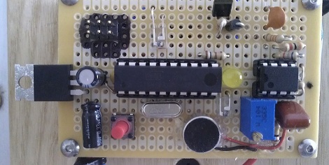
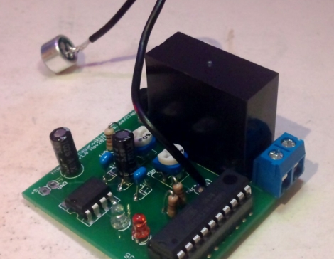
Like the clapper we saw last month, [Pete]’s version uses an ATtiny2313 and an electret mic. What sets [Pete]’s version apart from the vintage 80s model is the ability to dim the lights. Like any clapper, two hand claps within a second toggles the relay. Clapping three times within one second puts the lamp into fading mode. In this mode, the lights dim up and down with PWM until a fourth clap is detected.

[Pete] saw that the program memory in his ATtiny2313 wasn’t 100% full, so he added a few more capabilities. If you shine a laser onto his circuit, a relay trips and turns on a decorative moon lamp. There’s also a ‘lecture mode’ that feeds the microphone directly into the microcontroller to vary the PWM signal. The result is a light that brightens with more intense sound. Check that feature out after the break after the demo video of [Pete]’s Clever Clapper.

Continue reading “DIY Dimmable Clapper For All Your Lazy Lighting Needs”

DIY Clapper Is The Ideal Gift For The Laziest Person In Your Life

diy-clapper

If you haven’t yet wrapped up your Christmas shopping, you may want to consider building [AlanFromJapan’s] implementation of the ever-classic “Clapper”. With its theme song burned into the brain of anyone old enough to remember the 80s, the clapper was a wonderful device that certainly put the “L” in laziness.

Looking for an excuse to play around with an opamp and microphone [Alan] decided to build his own version of the Clapper based off this similar circuit, which he calls the ClapClap. He built the device using an electret mic that feeds a signal through a small amplifier on the way to the ADC of an ATmega328 microcontroller. The mcu constantly polls the ADC looking for the sound of clapping hands, a solution that works, but isn’t as clean as [Alan] wanted.

He went back to the drawing board, this time building a circuit around an ATtiny2313 microcontroller. Most of the other components remained the same, though the new, smaller design sports some nice PCBs he had made at Seeedstudio. Rather than constantly polling the ADC, this version of the ClapClap looks for peaks in the signal coming from the mic to identify the clapping of hands.

He says that the newer version works great, though he still has a software bug or two that need fixing before he parks himself on the couch for all eternity.

Shutter Trigger Remote With Some Nice Design Considerations

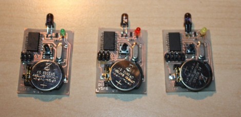
Here are the guts of [Lukasz’s] infrared camera remote control. He based it off of an existing design, but looked for places where improvements could be made. He felt the ATtiny2313 was a bit wasteful in this case. But further investigation led him to see why it was chosen. If you were to drop down to an ATtiny13 the ability to connect a crystal oscillator is lost (that chip only offers a 1-pin clock signal input) and the internal RC oscillator isn’t quite up to his standards for reliable IR communications.

Instead of driving the IR LED directly from an AVR pin he used a transistor in hopes that it will allow the maximum current to flow through the diode when in use. We’re not sure if it’s necessary, but we can see how it makes sense. Power is received from an unregulated 3 volt coin cell, so maybe as that voltage drops over time this will come into play.

Speaking of that coin cell, battery life is a concern here. [Lukasz] is using the sleep functions of the AVR after three seconds of use. This should keep the cell alive for quite a long time. But his 0 volt measurement is an anomaly with the multimeter he’s using. To get a precise measurement for tiny current flow you need extra equipment, like [Dave Jones’] uCurrent adapter.

The schematic for this Canon camera compatible project is only provided in Eagle format so we’ve embedded an image of it after the break for your convenience. You should have no problem making this work with a Nikon if you swap out some of the code from the TV-B-Gone shutter release we saw on Thursday.

Continue reading “Shutter Trigger Remote With Some Nice Design Considerations”