On the left side of the image, three lit candles are positioned next to each other, so that the flames merge. On the right side, an oscilloscope screen is shown displaying an oscillating waveform.

2025 One Hertz Challenge: A Flaming Oscillator And A New Take On The Candle Clock

Candle clocks were once an easy way to build a clock without using complex mechanical devices: just observe how quickly a thin candle burns down, mark an identical candle with periodic gradations, and you had a simple timer. These were the first candle-based timekeeping devices, but as [Tim]’s flicker-based oscillator demonstrates, they’re certainly not the only way to keep time with a flame.

Generally speaking, modern candles minimize flickering by using a wick that’s designed to balance the amount of wax and air drawn into the flame. However, when several candles are brought close together, their flames begin to interfere with each other, causing them to flicker in synchrony. The frequency of flickering is a function of gravity and flame diameter alone, so a bundle of three candles will flicker at a fairly constant frequency; in [Tim]’s case, it was about 9.9 Hz.

To sense this oscillation, [Tim] originally used a phototransistor to detect the flame’s light, but he wanted an even simpler solution. He positioned a wire just above the flame, so that as it flickered it would periodically contact the wire. A flame has a different dielectric constant than air does, so the capacitance between this and another wire wrapped around the bundle of candles fluctuates with the flame. To sense this, he used a CH32V003 microcontroller, which reads capacitance, performs some signal processing to get a clean signal, counts oscillations, and uses this time signal to blink an LED once a second. The final result is unusually mesmerizing for a blinking LED.

In something of the reverse of this project, we’ve also seen an oscillator used for an (artificial) candle. There’s also a surprising amount of science that can be learned by studying candles.

Continue reading “2025 One Hertz Challenge: A Flaming Oscillator And A New Take On The Candle Clock”

Custom Caliper Tracks For When You’re Going The Distance

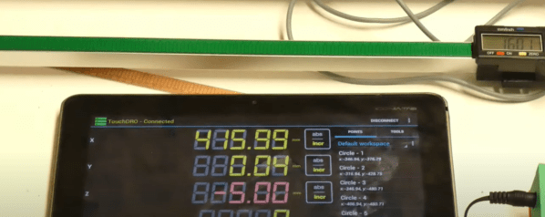
The working principle of digital calipers is mysterious enough that we’d never think to dismantle, much less improve them, right? Well, think again, as [Limi DIY] retrofits the processing element onto a custom track, extending the calipers measurement distance to a whopping 650 mm. Combined with a prior project to extract the measurement data, the result makes for a working multi-axis digital readout, a handy device for machine tools like a manual lathe or milling machine.

Digital calipers operate on the principle of measuring an array of variable capacitors. If we scratch our heads and look back at our physics notes, we’ll recall that the capacitance between two parallel conductive plates is linearly proportional to the surface area. By fixing one dimension of both plates and by sliding one plate over the other, we effectively change the area, giving ourselves a simple linear displacement sensor! (There are some classy error-correcting techniques too, and this [PDF] is a great place to look for more details.)

The theory takeaway is that this array of parallel plates can be embedded directly into a printed circuit board. We just need to know the dimensions. After some close measurement work, [Limi DIY] extracted the crucial measurements and fabbed a PCB with the pattern duplicated over 650 mm. After retrofitting the original processing element onto this new track, they had a working measurement device that’s far longer than the original!

If you’ve ever been tempted to disassemble your calipers but too nervous to bite off the investment, now’s your chance to follow along as [Lima DIY] demonstrates the gratuitous disassembly process for you in video format. And the fruits of their labor is also captured on a project post that includes the key dimensions if you’re looking to do the same thing.

If you’re looking for other ways to improve your calipers, why not start by giving them a major battery life boost.

Thanks to [absd] via [Jubilee Discord] for the tip!

Continue reading “Custom Caliper Tracks For When You’re Going The Distance”

How Many Punches Does It Take?

Do you ever wonder just how many punches you have thrown? The answer is going to be different if you happen to use a punching bag as part of your exercise routine. So is the case with the [DuctTapeMechanic] and while restoring an old speed ball punching bag, he decided to combine his passions for sports and electronics by adding a punch counter.

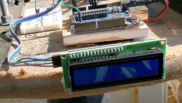
Perhaps most interesting in this build is the method used to monitor the bag. A capacitance proximity sensor most often used for industrial automation is mounted in the wooden base. He just calls it “an NPN capacitive sensor” without mentioning part number but these are rather easy to find from the usual places. It has no problem sensing each punch — assuming you swing strong enough so that the bag comes near the sensor. Two battery packs, an Arduino, and an optocoupler round out the bill of materials. We were a little disappointed not to see any duct tape in the construction of this project, but since the electronics are outside and exposed to the elements, maybe duct tape will be used to install a roof in a future episode.

The [DuctTapeMechanic] likes to repurpose items which would otherwise be thrown away, which is something to be applauded. The frame of this punching bag was welded from a discarded metal bed frame (a regular occupant of crawl spaces and self storage places), and you might remember he repurposed the electric motor from a discarded clothes dryer last month, changing it into a disk sander.

Continue reading “How Many Punches Does It Take?”

Capacitance Sensor Guide (AD7746)

capacitive_sensor

[Marcus] has written up his experiences using the AD7746 capacitance sensor. He used the SparkFun breakout board in conjunction with an Arduino. The available Arduino code wasn’t that great so he rewrote it to be easier to understand. The AD7746 is an I2C device that can be continuously read, but this doesn’t mesh well with the Wiring libraries. Additionally, the calibration routine from the data sheet is difficult to understand. He’s included all of the code he used plus a Processing sketch to help visualize the input which will hopefully make your experience with the chip much more smooth.