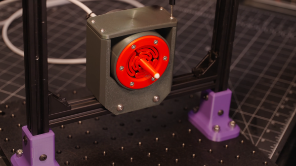
A grey box surrounding a circular red component is mounted on an aluminium extrusion frame. The circular red face has a protrusion extending from it with a white ball bearing at the tip.

Building A Micrometer-Level Displacement Sensor With 3D Printed Parts

Every experienced machinist knows the value of taking regular measurements. If one works carefully and checks dimensions frequently, it’s possible to make a part much more precise than could be made by relying on the machine’s accuracy alone. In a similar vein, it’s possible to make a measuring device out of comparatively crude parts, as long as their behavior is well understood. Related to both principles is [BubsBuilds]’s displacement sensor, which uses a 3D printed frame but reaches precision better than two micrometers.

Admittedly the printed parts aren’t the source of the sensor’s precision, that comes from an opto-interrupter. This design has a central stylus, one end of which contacts the object under measurement. The other end flattens to a knife-edge blade, which fits between the diodes of the opto-interrupter. As the stylus point is pressed in, the blade blocks off more light from reaching the photodiode, creating an output signal proportional to displacement. To keep the stylus from twisting or moving side-to-side, two flat, circular flexures hold the stylus in the center of a cylindrical housing.

[Bubs] printed several flexure variations to see how well they resisted and permitted various torques and forces, and a symmetrical flexure design proved best for his purposes. Once the sensor was assembled, he tested it against the measurements recorded by a laser confocal displacement sensor. This design was an update from a previous version, and it improved in a few regards: the non-linearity had decreased, and the repeatability was now better than two microns, though the range had been halved. Significantly, though, it’s now much easier to mount, making this an actually practical tool.

If, however, this doesn’t fit your needs, there are many other ways to build a linear displacement sensor, ranging from capacitive to magnetostrictive. On the manual side of things, we’ve also covered a comparison of calipers.

Continue reading “Building A Micrometer-Level Displacement Sensor With 3D Printed Parts”

Series of purple and red mechanisms are stretched from left to right. Almost like arrows pointing right.

Compliant Mechanism Shrinks Instead Of Stretching

Intuitively, you think that everything that you stretch will pull back, but you wouldn’t expect a couple of pieces of plastic to win. Yet, researchers over at [AMOLF] have figured out a way to make a mechanism that will eventually shrink once you pull it enough.

Named “Counter-snapping instabilities”, the mechanism is made out of the main sub-components that act together to stretch a certain amount until a threshold is met. Then the units work together and contract until they’re shorter than their initial length. This is possible by using compliant joints that make up each of the units. We’ve seen a similar concept in robotics.

The picture reads "Excessive vibrations? / It tames them by itself... / ... by switching them off! Bridge undergoing harmonic oscillation about to crumble on the left and mechanisms on the right.

Potentially this may be used as a unidirectional actuator, allowing movement inch by inch. In addition, one application mentioned may be somewhat surprising: damping. If a structure or body is oscillating through a positive feedback loop it may continue till it becomes uncontrollable. If these units are used, after a certain threshold of oscillation the units will lock and retract, therefore stopping further escalation.

Made possible by the wonders of compliant mechanics, these shrinking instabilities show a clever solution to some potential niche applications. If you want to explore the exciting world of compliance further, don’t be scared to check out this easy to print blaster design!

Continue reading “Compliant Mechanism Shrinks Instead Of Stretching”

Bendy Straws

Compliant Mechanisms Hack Chat

Join us on Wednesday, January 26 at noon Pacific for the Compliant Mechanisms Hack Chat with Amy Qian!

When it comes to putting together complex mechanisms, we tend to think in a traditional design language that includes elements like bearings, bushings, axles, pulleys — anything that makes it possible for separate rigid bodies to move against each other. That works fine in a lot of cases — our cars wouldn’t get very far without such elements — but there are simpler ways to transmit force and motion, like compliant mechanisms.

Compliant mechanisms show up in countless products, from the living hinge on a cheap plastic box to the nanoscale linkages etched into silicon inside a MEMS accelerometer. They reduce complexity by putting the elasticity of materials to work and by reducing the number of parts it takes to create an assembly. And they can help make your projects easier and cheaper to build — if you know the secrets of their design.

join-hack-chatAmy Qian, from the Amy Makes Stuff channel on YouTube,  is a mechanical engineer with an interest in compliant mechanisms, so much so that she ran a workshop about them at the 2019 Superconference. She’ll stop by the Hack Chat to share some of what she’s learned about compliant mechanisms, and to help us all build a little flexibility into our designs.

Our Hack Chats are live community events in the Hackaday.io Hack Chat group messaging. This week we’ll be sitting down on Wednesday, January 26 at 12:00 PM Pacific time. If time zones have you tied up, we have a handy time zone converter.


Continue reading “Compliant Mechanisms Hack Chat”