My Life In The Connector Zoo

“The great thing about standards is that there are so many to choose from.” Truer words were never spoken, and this goes double for the hobbyist world of hardware hacking. It seems that every module, every company, and every individual hacker has a favorite way of putting the same pins in a row.

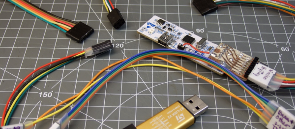
We have an entire drawer full of adapters that just go from one pinout to another, or one programmer to many different target boards. We’ll be the first to admit that it’s often our own darn fault — we decided to swap the reset and ground lines because it was convenient for one design, and now we have two adapters. But imagine a world where there was only a handful of distinct pinouts — that drawer would be only half full and many projects would simply snap together. “You may say I’m a dreamer…”

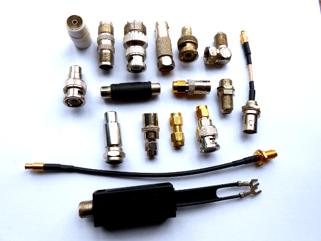
This article is about connectors and standards. We’ll try not to whine and complain, although we will editorialize. We’re going to work through some of the design tradeoffs and requirements, and maybe you’ll even find that there’s already a standard pinout that’s “close enough” for your next project. And if you’ve got a frequently used pinout or use case that we’ve missed, we encourage you to share the connector pinouts in the comments, along with its pros and cons. Let’s see if we can’t make sense of this mess.

Continue reading “My Life In The Connector Zoo”

Co-Exist With Your Coax: Choose The Right Connector For The Job

Just a selection from the author's unholy assortment of adaptors.
Just a selection from the author’s unholy assortment of adaptors.

If you do any work with analogue signals at frequencies above the most basic audio, it’s probable that somewhere you’ll have a box of coax adaptors. You’ll need them, because the chances are your bench will feature instruments, devices, and modules with a bewildering variety of connectors. In making all these disparate devices talk to each other you probably have a guilty past: at some time you will have created an unholy monster of a coax interface by tying several adaptors together to achieve your desired combination of input and output connector. Don’t worry, your secret is safe with me.

Continue reading “Co-Exist With Your Coax: Choose The Right Connector For The Job”

How To Properly Crimp Electronics Connectors

Putting crimp connectors on wires is one of the most tedious things you’ll do. It’s not easy, either, unless you have some practice. Before you start digging in to a pile of connectors, crimp terminals, and wire, it’s a good idea to know what you’re getting into and Gogo:tronics has a great tutorial on how to crimp electronics connectors.

Crimping connectors onto wires requires the right tool, and the most important for this task is – surprise – the crimping pliers. These pliers press the crimping wings of the connector into each other, a task made much easier on the non-ratcheting pliers if you use a rubber band to hold the jaws of the crimping pliers open just enough to hold a crimp connector.

The general theory for crimping all types of connectors is to strip a little bit of insulation off the wire. Then, put the connector into a suitably sized space in the jaws, insert the wire, and crimp it down. For non-ratcheting pliers, it’s suggested the connector be re-crimped with the next smallest hole in the jaws.

There are a few connector-specific tips for the most common connector types, too. Dupont connectors – those flat, black connectors with a 0.1″ pitch – go together like you think they would, but for larger connectors – VH and XH-style – it’s important to use the right wire gauge and not to squish the square female part of the connector.