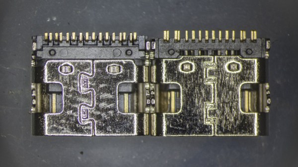
Anyone who’s ever put together a bill-of-materials for an electronic device will be familiar with the process of scouring supplier catalogs and data sheets for the best choice of components. The trick is to score the best combination of price and performance for the final product, and for those unused to the process, there are always seemingly identical products with an astonishingly wide variety of prices. It’s a topic [Timon] explores in a Twitter thread, examining a 20-cent in quantity of 100 USB-C socket alongside one that costs only 5 cents, and his teardown provides a fascinating insight into their manufacture.
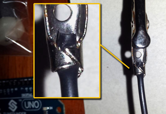
The parts look so nearly identical that while it’s possible to differentiate between them visually, it’s near impossible to work out which was the cheaper. Some tiny features such as a crack in a metal fold or a bit less plating on the contacts emerge, but even then it’s no guide to the quality as they don’t appear on the same part. It’s only when the metal shell is removed to expose the underlying plastic moulding that more clues emerge, as one moulding is more complex than the other. The more complex moulding provides a better and more reliable fit at the expense of a much more costly moulding process, so at last we can not only identify the more expensive part but also see where the extra cash has gone. It’s a subtle thing, but one that could make a huge difference to the performance of the final assembly and which makes for a fascinating expose for electronic design engineers.
If connectors are your thing, there’s a wealth of fascinating information in their history.