One characteristic of adding PV solar to homes is a massive increase in high-voltage and high-current DC installations. With this comes a need for suitable breakers, but without the requisite knowledge it can be easy to set up a fire hazard. There is also the issue of online shopping platforms making it easy to get fuses and breakers that may not be quite as capable as they claim, never mind being rated for DC use.
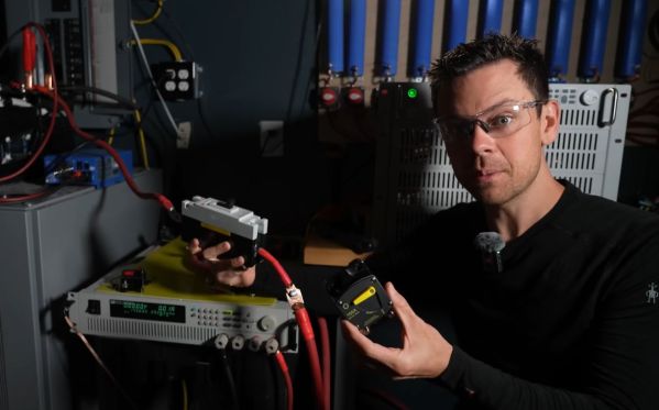
Recently [Will Prowse] had a poke at a range of common purportedly DC-rated breakers from everyone’s favorite US-based seller of tat, to see whether they should be bought or avoided at all cost. Perhaps unsurprisingly the cheap breakers are about as dodgy as you’d imagine. With a hundred plus amps flowing through them they get surprisingly crispy, even if they generally did their job. Minus the few that arrived in a broken condition, of course.
Ultimately [Will] found that the molded case circuit break (MCCB) by one ‘DIHOOL’ performed the best. Compared to the competition, it is much larger and has sizeable terminals that avoid the quaint heat-soaking issues seen with the cheap-and-cheerful rest. At a mere $34 for the 125A-rated version, it’s still a fraction of the cost of a comparable Eaton MCCB, but should upset your insurance company significantly less than the alternatives.
Don’t forget to add in fuses, with [Will] testing a range of cheapo 12V DC fuses, to see which one will prevent fires, and which one cause them. Unsurprisingly, some of them like the Bojack-branded ones ran very hot, making them more of a liability than an asset.
As for what makes DC breakers so different from AC one is that the extinguishing point of a DC arc is much steeper, which means that an AC breaker is likely to fail to extinguish the arc when used for DC applications. This is why a properly rated and ideally certified breaker is essential, and also not really the point where you want to start saving money.
Continue reading “Testing Cheap DC Breakers And How To Not Start Fires”