Git With Eagle: Add Meaning to Diff

a-glimpse-of-git-with-eagleWe love Git. We know everyone has their favorite version tracking tools. But even those that don’t care for Git should see the value of getting meaningful Diff data from tracking Eagle layout files.

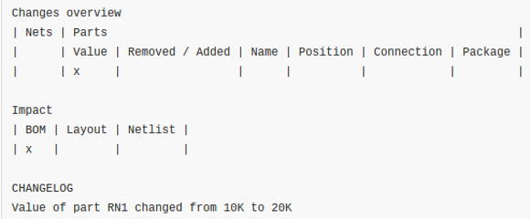
Was that last sentence just gibberish to you? Let’s take a step back. A few years ago it was impossible to use version control with Eagle at all because the schematic and PCB layout software used to save its files as binaries. But then Cadsoft transitioned to saving Eagle files as XML. This opened the door for things like scripting to rename parts en masse and to track the files under version control. One problem with the latter has been that performing a Diff on two different versions of a file results in XML changes that are probably not human readable. [Patrick Franken] wrote this script to add at least a glimmer of meaning.

We’d love to see some kind of side-by-side highlighting on the schematic or board renderings themselves. But that’s quite a ways off if we ever actually see it. For now his script will take the Diff and print out the tables seen above denoting which types of changes were made from one version to the next. It’s a start, and we hope it inspires even more work in this area.

Coding New Parts In Eagle

chip

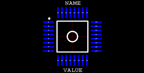
Making new parts in Eagle CAD isn’t the easiest thing in the world, especially if you’re dealing with a package that isn’t in one of the default libraries. Usually, making a new part means digging out a datasheet and drawing a new part in Eagle. A better solution would be to generate new parts with code – define the number of pads, the shape of the pads, the symmetry of the chip, and so forth. [Joost]’s madparts does just that, allowing anyone to create new parts in Eagle by entering numbers instead of drawing lines.

The idea behind madparts is to code new entries in Eagle libraries with Coffeescript. It has instant graphical feedback for the part you’re designing, and is able to import from and export to Eagle libraries. A KiCAD-enabled release is coming soon, but until then, madparts looks like a great way to create your own parts in weird packages in Eagle.

Turning PCBs Into Art

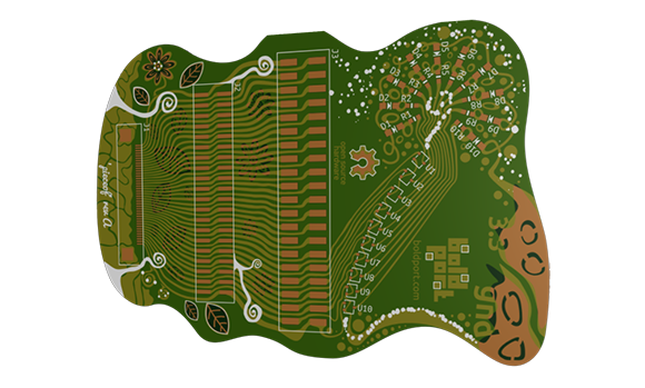
Designing a circuit, laying out a board, and sending it off to be fabbed is so easy anyone can do it. A lot of people are, in fact, and with the traditional tools like KiCAD and Eagle, a lot of different boards look very, very similar. You could always add some cool silkscreen graphics to your board to make it stand out, but [Saar] has a better solution: it’s called PCBmodE, and it allows you to draw circuits artistically instead of the 45° angles we’ve become so accustomed to.

PCBmodE takes the parts, pads, signals, and vias for boards stored in JSON files and converts them to an SVG representation. The file is then routed (manually, but [Saar] is working on automated routing) and Gerberized so it can be sent off to a production house.

You can grab PCBmodE over on bitbucket, but right now it’s still a very early version. Vias and copper pours are working, but [Saar] has only fabbed this board so far.

Assigning New Packages To Eagle PCB Components

adafruit-eagle-component-creation-tut

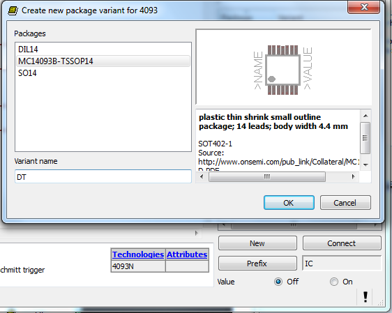
If you’ve spent any time at all laying out your own circuit boards we’re sure you’ve run into the issue of not having the right component or package available in the standard libraries. If it’s a common part, chances are the symbol definition will be there.  But perhaps the footprint you want to use is missing? Here’s an easy to follow tutorial which demonstrates how to assign new packages to existing Eagle PCB components. It even shows the basics of how to tweak the footprint to fit your needs (like making SMD footprints easier to hand solder).

This will not teach you how to make your own custom symbols, or how to build packages from scratch. But it will let you locate the package you want to use from a different component, then copy it to your own library for use with different parts. And the techniques shown make this a quick and relatively painless process.

We certainly don’t want to start another comment quagmire like the recent PIC v. AVR discussion. But we’ve used both Kicad and Eagle rather extensively and feel that neither one has really mastered part/footprint creation in a user-friendly way. We like Kicad’s total separation of footprints from components, and it’s myriad of parameters which can be used to tweak the layout. But if you use the same components frequently, Eagle’s standard of linking parts and footprints does end up saving a lot of time. What do you think?

Taking The Pain Out Of Making Custom Eagle Parts

eagle

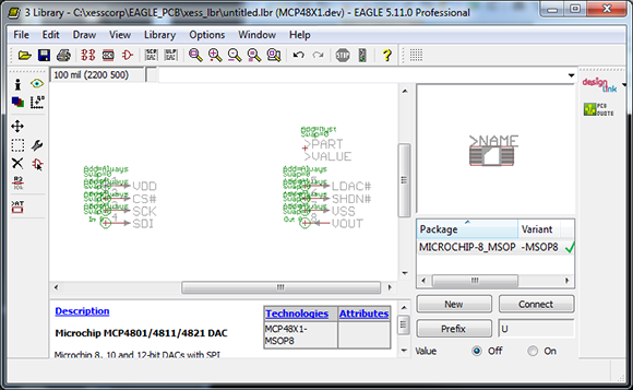
Cadsoft’s Eagle is a great tool for the independent maker. It’s a relatively easy to use PCB layout program with a ton of part libraries available for just about any project. If you’re using a part this isn’t included in these libraries, though, creating them by hand is a pain. [Dave] sent in a project he’s been working on that makes parts for Eagle with a Perl script, allowing for easy creation of custom parts that aren’t included in any library.

One thing that’s really convenient for custom Eagle parts is that most components are DIPs or some sort of leaded SMD component. [Dave]’s script takes the dimensional data from any chip’s datasheet and creates a custom outline for each part. The inputs and outputs can also be ripped directly from the datasheet and assigned to the footprint, making for a relatively automated process that creates custom parts in Eagle. Now for someone to use this script with a little OCR to make a ‘create Eagle part from PDF’ app…

Panelizing PCBs In Eagle

final_panel

A lot of the board houses out there including Seeed and ITead studios have a fixed size for circuit boards before the price goes up. A one-inch square board costs the same as a much larger 5cm x 5cm board, making panelized PCBs a great way to get more boards for the same amount of money. Trying to panelize a board in Eagle with copy and paste is a chore without the right tools, though, so we’re happy to see a great panelization tutorial from [Victor].

To panelize one of his boards for a PCB order, [Victor] used one of Eagle’s User Language Programs to duplicate the part names on the additional boards. After that, it was a simple matter of running a CAM job to generate the necessary Gerber files.

Of course once the boards arrive, you’ll have to cut them apart from each other. This can be done with everything from a Dremel to a hack saw to a metal shear, but we’re wondering what other Hackaday readers are using to cut up PCBs. Leave a note in the comments with your preferred method of depanelization.

Making Eagle Work With Circuits.io

IO

Ever so slowly, we’re inching towards a world of Internet-based electronic design tools. The state of these tools, including Upverter and other cloud-based solutions, hasn’t been all that great until now; with any new piece of schematic capture and PCB layout software, the libraries will be woefully inadequate in the beginning. This is about to change, because circuits.io is now allowing Eagle libraries to be imported.

As you may well be aware, Eagle is the de facto standard for homebrew and hobbyist schematic capture and board layout software. Even though Eagle isn’t open source and is limited to rather small PCBs with the free version, somehow Eagle has retained its popularity, most likely due to the huge number of component libraries available.

By allowing users and designers to import Eagle libraries, the folks at circuits.io are capitalizing on a huge amount of work done by designers and engineers over the years in creating custom Eagle parts for just about every component imaginable. It’s a great accomplishment for the circuits.io team and a boon for anyone wanting to move their PCB design tools over to the cloud.