We’re no strangers to DIY environmental monitors around these parts, in fact, it seems like that’s one of the most common projects hackers take on when confronted with the power of a modern Internet-connected microcontroller. But among such projects, this miniature nRF52-based weather station built by [Andrew Lamchenko] is among the most polished we’ve seen.
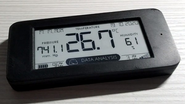
Externally, this looks as though it could easily be a commercial product. The graphical interface on the ePaper display is very well designed, delivering plenty of data while still looking attractive enough to hang in the kitchen. The enclosure is 3D printed, but [Andrew] poured enough elbow grease into sanding and polishing the front that you might not realize it at first glance.
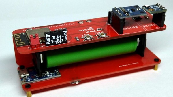
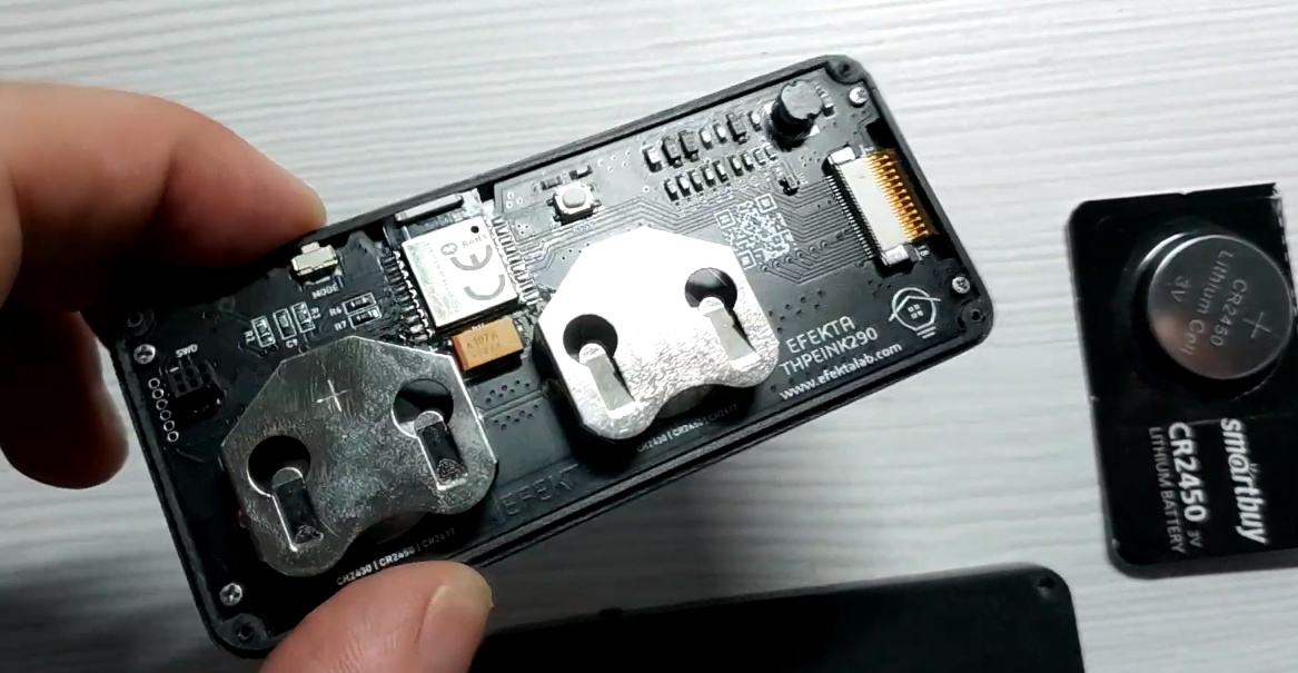 Internally it uses the popular BME280 sensor to detect temperature, humidity, and barometric pressure, though the custom PCB is also compatible with the similar SI7021 and HTU21D sensors if you want to switch things up.
That said, you really want the ability to measure pressure, as it allows the firmware to do its own basic weather forecasting. All the collected data is beamed out over Bluetooth Low Energy (BLE), where it can be collected by the open source MySensors IoT framework, but we imagine it wouldn’t take much work to integrate it into your home automation system of choice.
As excited as we might be about the prospect of repurposing things such as electronic shelf labels, we’re happy to see the prices for general purpose electronic paper screens finally dropping to the point where projects of this caliber are within the means of the hacker crowd.
Continue reading “NRF52 Weather Station Gives Forecast With Style”