Is The Frequency Domain A Real Place?

When analyzing data, one can use a variety of transformations on the data to massage it into a form that works better to tease out the information one is interested in. One such example is the application of the Fourier transform, which transforms a data set from the time domain into the frequency domain. Yet what is this frequency domain really? After enticing us to follow the white rabbit down a sudden plummet into the intangible question of what is and what is not, [lcamtuf] shows us around aspects of the frequency domain and kin.

One thing about the (discrete) Fourier transform is that it is excellent at analyzing data that consists out of sinewaves, such as audio signals. Yet when using the Fourier transform for square waves, the resulting output is less than useful, almost as if square waves are not real. Similarly, other transforms exist which work great for square waves, but turn everything else into meaningless harmonics. Starting with the discrete cosine transform (DCT), this gets us into Walsh and Hadamard matrices and the Walsh-Hadamard Transform (WHT), and their usage with transforming data from the time into the frequency domain.

Ultimately it would seem that the frequency domain is as real as it needs to be, albeit that its appearance is wholly dependent on the algorithm used to create it, whether this the DFT, DCT, WHT or something else entirely.

Tearing Into Delta Sigma ADCs Part 2

In part one, I compared the different Analog to Digital Converters (ADC) and the roles and properties of Delta Sigma ADC’s. I covered a lot of the theory behind these devices, so in this installment, I set out to find a design or two that would help me demonstrate the important points like oversampling, noise shaping and the relationship between the signal-to-noise ratio and resolution.

Modulator Implementation

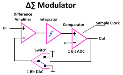
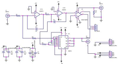
modulatorCheck out part one to see the block diagrams of what what got us to here. The schematics shown below are of a couple of implementations that I played with depicting a single-order and a dual-order Delta Sigma modulators.

schematicBasically I used a clock enabled, high speed comparator, with two polarities in case I got it the logic backwards in my current state of burn out to grey matter ratio. The video includes the actual schematic used.

Since I wasn’t designing for production I accepted the need for three voltages since my bench supply was capable of providing them and this widget is destined for the drawer with the other widgets made for just a few minutes of video time anyway. Continue reading “Tearing Into Delta Sigma ADCs Part 2”

Tearing Into Delta Sigma ADC’s

It’s not surprising that Analog to Digital Converters (ADC’s) now employ several techniques to accomplish higher speeds and resolutions than their simpler counterparts. Enter the Delta-Sigma (Δ∑) ADC which combines a couple of techniques including oversampling, noise shaping and digital filtering. That’s not to say that you need several chips to accomplish this, these days single chip Delta-Sigma ADCs and very small and available for a few dollars. Sometimes they are called Sigma-Delta (∑Δ) just to confuse things, a measure I applaud as there aren’t enough sources of confusion in the engineering world already.

I’m making this a two-parter. I will be talking about some theory and show the builds that demonstrate Delta-Sigma properties and when you might want to use them.

Continue reading “Tearing Into Delta Sigma ADC’s”