RasPi FM Transmitter

Easily Turn Your Raspberry Pi Into An FM Transmitter

Have you ever wanted to be your own radio DJ? [Kevin] has made it easier than ever with his Raspberry Pi FM Transmitter program. The program is written in C. [Kevin] has made source code is available along with a compiled binary.

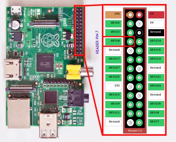
PIFM allows you to load up any audio file and specify a frequency to transmit. The program will then use PWM to modulate the audio sample through the Pi’s GPIO4 pin. [Kevin] claims that the RasPi alone will only transmit around a 10 cm distance. He says that making a simple antenna out of a jumper wire can increase the distance to around 100 meters. All you have to do is hook up the wire to the GPIO4 pin to drastically increase the range.

The legality of such a transmitter will vary from place to place, so be sure to check out your local regulations before you go transmitting audio on regulated frequencies. If this kind of thing is interesting to you, you may want to investigate ham radio. It’s not all Morse code and old fogies. Some people claim it’s a hacker’s paradise.

[via Reddit]

TDOA (Time Difference Of Arrival) Directional Antenna

tdoa-antenna-tutorial

We have posted articles in the past on directional antennas such as Yagi antennas used for transmitter hunting otherwise known as fox hunting. Those types of antennas and reception suffer from one major drawback, which is as you get close to the transmitter the S meter will go full scale. At which time the transmitted signal appears to be coming from all directions. To correct for this problem you need to use clever signal attenuators or change to a poor receiving antenna as well as tuning off frequency effectively making your receiver hard of hearing so that only the direct path to the transmitter is loudest.

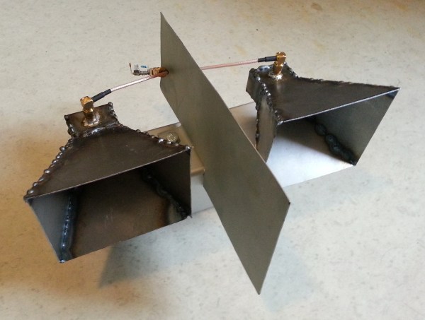
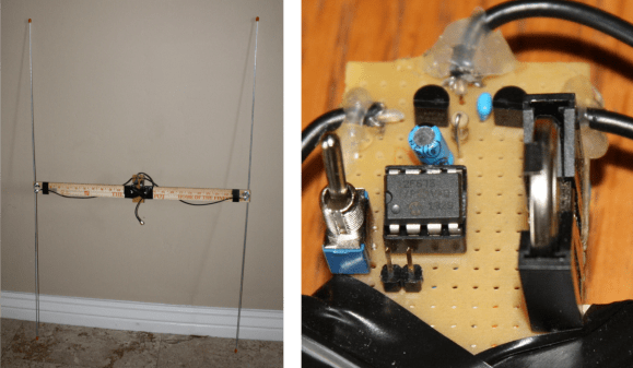
There is another popular type of antenna that you can build yourself called a TDOA which stands for Time Difference of Arrival. [Byon Garrabrant N6BG]  shared a short video tutorial on the functionality of his home built TDOA antenna. Effectively this is an active antenna that uses a 555 chip or, in [Byon’s] case, a PIC chip to quickly shift between two receiving dipole antennas at either end of a shortened yardstick. In his explanation you learn that as the antenna ends move closer or farther from the source a 640 Hz generated audio tone will go from loud to very soft as the antennas become equal distance from the source. This type of directional reception is not affected by signal strength. This means you can be very close to a powerful transmitter and it will still function as a good directional antenna.

The current circuit diagram, BOM and source code are all available on [Byon’s] TDOA page.

The reason [Byon] used a programmable PIC instead of the 555 for his design is because he wants to add a few more modifications such as feeding back the audio output to the PIC in order to programmatically turn on a left or right LED indicating the direction of the transmitter. Furthermore, he plans on adding a third antenna in a triangular configuration to programmatically control a circle of 6 LEDs indicating the exact direction of the signal. When he finishes the final modifications he can drive around with the antenna array on his vehicle and the circle of LEDs inside indicating the exact direction to navigate.

We look forward to seeing the rest of the development which might even become a kit someday. You can watch [Byon’s] TDOA video after the break.

Continue reading “TDOA (Time Difference Of Arrival) Directional Antenna”

Improve Your HT Ham Radio By Adding A Counterpoise Antenna Wire

counterpoise

We found an interesting tip that might just improve the performance of those small affordable handheld ham radios called a “Handy Talky” or HT for short in ham vernacular. [RadioHamGuy] posted an interesting video on adding a counterpoise antenna wire to an HT. He claims it will noticeably improve both transmit and receive by making a quarter-wave monopole into a makeshift dipole antenna system.

Per his instructions you basically add a short wire to the antenna’s outer ground connection or to an equivalent case screw that’s electrically connected to the antenna’s ground side. Apparently this can be referred to as a Tiger Tail and does make it look like your HT has a tail. You would construct a counterpoise antenna wire 11.5 inch for VHF, 6.5 for UHF and about 19.5 inches for an OK performing dual band VHF/UHF radio.

Normally with a handheld radio the counterpoise (ground) is your own body as you are holding the HT. This is because the capacitance of your body makes a good counterpoise under normal conditions. It would be interesting to hear what others find for performance when adding a counterpoise antenna wire.

You can watch [RadioHamGuy’s] full construction tutorial video for multiple radio types after the break.

Continue reading “Improve Your HT Ham Radio By Adding A Counterpoise Antenna Wire”

Build A Cheap Airplane ADS-B Radio Receiving Tracking Station

Do you have commercial or general aviation flying over your home or near your home? Would you like to know more about these airplanes: identity, heading, speed, altitude and maybe GPS data along with even more information? Well then [Rich Osgood] has just the project for you and it’s not that expensive to set up. [Rick] demonstrates using a cheap USB dongle European TV tuner style SDR (software defined radio) tuner that you can get for under $30 to listen in on the Automatic Dependent Surveillance-Broadcas (ADS-B) (dead link, try the Internet Archive version) 1090 MHz mode “S” or 978 MHz mode “UAT” signals being regularly transmitted from these aircraft.

He steps us through configuring the radio to use a better antenna for improved reception then walks through detailed software installation and set up to control the radio receiver as well as pushing the final decoded data to mapping software. This looks like a fascinating and fun project if you live near commercial airways. You won’t need a license for this hack because you’re only listening and not transmitting, plus these are open channels which are legal to receive.

There are some frequencies you are not legally allowed to eavesdrop on—private communications for residential wireless telephones and cellular frequencies to name just a few (Code of Federal Regulations Title 47, Part 15.9). So remember you do have to be careful and stay within legal frequencies even if your equipment is not restricted from such reception. Also note that just because you have a legal right to intercept conversations or data on some frequencies it could be illegal to publicly share the intercepted content or any details on the reception or decoding (just saying for the record).

We wonder if [Rick] could partner with [G. Eric Rogers] to upgrade [Eric’s] motorized telescope airplane tracking system to extrapolate the radio telemeter data into vector data so his Arduino can track without relying on a video feed. That merger might just get them both on a short TSA list.

Join us after the break for some extra informational links and to watch the video on setup, installation and usage of this cheap airplane tracking rig.

Continue reading “Build A Cheap Airplane ADS-B Radio Receiving Tracking Station”

Tape Measure VHF Yagi Antenna

tap measure yagi vhf antenna

Radio direction finding and fox hunting can be great fun and is a popular activity with amateur radio (ham radio) enthusiasts. These antennas are great and are not only good for finding transmitters but also will greatly increase directional distance performance including communicating with satellites and the international space station (ISS).

[jcoman] had a nephew who was interested in learning about amateur radio so [jcoman] figured building and using a cheap and portable 2 meter band VHF Yagi style beam antenna would be the perfect activity to captivate the young lad’s interest in the hobby.

His design is based on [Joe Leggio’s] (WB2HOL) design with some of his own calculated alterations. We have seen DIY Yagi antenna designs before but what makes this construction so interesting is that the elements come together using bits of cut metal tape measure sections. These tape measure sections allow the Yagi antenna, which is normally a large and cumbersome device, to be easily stowed in a vehicle or backpack. When the antenna is needed, the tape measure sections naturally unfold and function extremely well with a 7 dB directional gain and can be adjusted to get a 1:1 SWR at any desired 2 m frequency.

The other unique feature is that the antenna can be constructed for under $20 if you actually purchase the materials. The cost would be even less if you salvage an old tape measure. You might even have the PVC pipes, hose clamps and wire lying around making the construction nearly free.

We were quite surprised to find that such a popular antenna construction method using tape measure elements had not yet been featured on Hackaday. For completeness this is not the only DIY tape measure Yagi on Instructables so also check out [FN64’s] 2 m band “Radio Direction Finding Antenna for VHF” and [manuka’s] 70 cm band “433 MHz tape measure UHF antenna” postings. The other Yagi antenna designs featured on Hackaday were “Building a Yagi Uda Antenna” and “Turning an Easter Egg Hunt into a Fox Hunt” but these designs were not so simple to construct nor as cleverly portable.

Long-distance High Frequency APRS Tracking Using The FreeTrak63

FT63_857_etrex

If you dabble in the ham radio hobby we’re sure you’ve heard of GPS position monitoring or tracking using APRS packet data commonly transmitting over the VHF ham band and FM modulated. One of the issues you’ll face using this common method is range limitations of VHF. [Mike Berg] a.k.a [N0QBH ] tipped us off to his latest project to greatly increase the range of a standalone APRS system utilizing the HF bands on single-sideband (SSB).

There are some unique challenges transmitting packet data using SSB over HF bands.  High Frequency APRS has been around for decades utilizing FSK AX.25 packet transmissions at 300 baud, but it was quite susceptible to noise and propagation aberrations. More recently PSK-31 at the slower 31 baud speed helped alleviate many of these issues. [Mike] utilized the somewhat updated APRS with PSK-63 and the “APRS Messenger” program to overcome these challenges. [Mike’s] hardware solution consists of a PIC 16F690 micro which is coded to receive data from a GPS receiver, convert it into PSK-63 and then transmit on 30 meters over an attached HF radio. A second receiving station or stations at great distances can pick up and decode the transmission using the “APRS Messenger” program connected to the receiving radio over the computer’s soundcard. The program can then forward the tracking information, if good, to tracking websites like FindU.com and APRS.FI.

You can build your own FreeTrak63 by downloading [Mike’s] parts list, assembly code, HEX file, manual and schematic. The PCB is available on OSH Park if you don’t want to make your own or wire point-to-point. Let’s not forget to mention how hackable this hardware is, being really just an eight bit DAC, micro, serial in and radio out. One could reprogram this hardware to do other modulation schemes like AX.25 packet or MFSK16, the sky’s the limit. If short-distance on VHF with existing Internet linked receiver networks using an Arduino compatible platform is more to your taste, then checkout the Trackuino open source APRS Tracker.

Diagnose And Repair A Yaesu FT-7800 Ham Radio

Yaesu FT-7800 Ham Radio

[Alan Wolke] aka [w2aew] was challenged to repair a friends Yaesu FT-7800 ham radio. This radio operates on two ham bands, 2 m VHF and 70 cm UHF. The complaint was that the 2 m side was not working but the 70 cm was transmitting fine. Alan started by verifying the complaint using a Bird watt meter with a 50 watt slug and terminating the signal into a 50 W dummy load. [Allen’s] bird meter is the type that has an RF sampler that can be connected to an oscilloscope for added signal viewing and validation.

After verifying that the radio was not working as described, Alan starts by glancing over the circuit board to look for any obvious damage. He then walks us through a block diagram as well as a circuit diagram of the FT-7800 radio before stepping us through the troubleshooting and diagnostics of radio repair. Even when he realizes he might have found the problem he still steps us through the remainder of his diagnostics. The skills and knowledge that Alan shares is extremely valuable to anybody looking to repair radios.

Spoiler alert. At the end of the first video he determines that the pin diodes near the final VHF output were bad. In the second video he reveals that he could no longer source these bad components. Through some clever evaluation of a more current Yaesu radio, [Allen] was able to find suitable replacement components. Lesson two ends with some surface mount solder rework tips as well as testing that the repair was successful.

And just in case you don’t know what a pin diode is, or is used for, Alan shares a third video covering just what this component is and does in a radio. You can follow the jump to watch all three videos.

Continue reading “Diagnose And Repair A Yaesu FT-7800 Ham Radio”