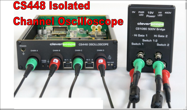
[Bart Schroder] was busy designing high voltage variable speed motor drives and was lamenting the inability of a standard scope to visualise the waveforms around the switch transistors. This is due to the three phase nature of such motors being driven with three current waveforms, out of phase with each other by 120 degrees, where current flows between each pair of winding taps, without being referenced to a common notion of ground. The average scope on your bench however, definitely is ground-referenced, so visualising such waveforms is a bit of a faff. Then there’s the fact that the motors run at many hundreds of volts, and the prospect of probing that with your precious bench instrument is a little nerve-wracking to say the least. The solution to the issue was obvious, build your own isolated high voltage oscilloscope, and here is the Cleverscope CS448 development journey for your viewing pleasure.
The scope itself is specification-wise nothing too flash, it’s the isolated channels that make it special. It does however have some niceties such as an extra eight 100 Mbps digital inputs and a handy 65 MHz signal generator. Also, don’t reach for your wallets just yet, as this is a specialised instrument with an even smaller potential user base than a normal scope, so these units are rather pricey. That all said, it’s not the existence of the scope that is the focus here, it’s the journey from problem to solution that interests us the most. There is much to learn from [Bart’s] journey, for example, where to place the frontend ADC? Isolated side or not? The noise floor of the signal chain dictated the former.
Continue reading “Isolated Oscilloscope Design Process Shows How It’s Done”


