Lowering The Boom On Yagi Element Isolation

Antenna design can be confusing, to say the least. There’s so much black magic that goes into antennas that newbies often look at designs and are left wondering exactly how the thing could ever work. Slight changes in length or the angle between two elements result in a vastly different resonant frequency or a significant change in the antenna’s impedance. It can drive one to distraction.

Particularly concerning are the frequent appearances of what seem to be dead shorts between the two conductors of a feedline, which [andrew mcneil] explored with a pair of WiFi Yagi antennas. These highly directional antennas have a driven element and a number of parasitic elements, specifically a reflector behind the driven element and one or more directors in front of it. Constructive and destructive interference based on the spacing of the elements and capacitive or inductive coupling based on their length determine the characteristics of the antenna. [Andrew]’s test antennas have their twelve directors either isolated from the boom or shorted together to the shield of the feedline. In side-by-side tests with a known signal source, both antennas performed exactly the same, meaning that if you choose to build a Yagi, you’ve got a lot of flexibility in what materials you choose and how you attach elements to the boom.

If you want to dive a little deeper into how the Yagi works, and to learn why it’s more properly known as the Yagi-Uda antenna, check out our story on their history and operational theory. And hats off to [andrew] for reminding us that antenna design is often an exercise in practicality; after all, an umbrella and some tin cans or even a rusty nail will do under the right circumstances.

Continue reading “Lowering The Boom On Yagi Element Isolation”

Accidental Satellite Hijacks Can Rebroadcast Cell Towers

A lot of us will use satellite communications without thinking much about the satellite itself. It’s tempting to imagine that up there in orbit is a communications hub and distribution node of breathtaking complexity and ingenuity, but it might come as a surprise to some people that most communications satellites are simple transponders. They listen on one frequency band, and shift what they hear to another upon which they rebroadcast it.

This simplicity is not without weakness, for example the phenomenon of satellite hijacking has a history stretching back decades. In the 1980s for example there were stories abroad of illicit trans-atlantic serial links nestling as unobtrusive single carriers among the broad swathe of a broadcast satellite TX carrier.

Just sometimes, this phenomenon happens unintentionally. Our attention was drawn to a piece by [Harald Welte] on the unintended rebroadcast of GSM base station traffic over a satellite transponder, and of particular interest is the presentation from a conference in 2012 that it links to. The engineers show how they identified their interference as GSM by its timing frames, and then how they narrowed down its source to Nigeria. This didn’t give them the uplink in question though, for that they had to make a downconverter from an LNB, the output of which they coupled to an aged Nokia mobile phone with a wire antenna placed into an RF connector. The Nokia was able to decode the cell tower identification data, allowing them to home in on the culprit.

There was no fault on the part of the GSM operator, instead an unterminated port on the uplink equipment was enough to pick up the GSM signal and introduce it into the transponder as a parasitic signal for the whole of Europe and Africa to hear. Meanwhile the tale of how the engineers identified it contains enough detective work and outright hardware hacking that we’re sure the Hackaday readership will find it of interest.

If satellite hacks interest you, how about reading our thread of posts on the recapture of ISEE-3, or maybe you’d like to listen for a lost satellite from the 1960s.

Thanks [Kia] for the tip.

Solderless Breadboard Parasitics

Solderless breadboards are extremely handy. You always hear, of course, that you need to be careful with them at high frequencies and that they can add unwanted capacitance and crosstalk to a circuit. That stands to reason since you have relatively long pieces of metal spaced close together — the very definition of a capacitor.

[Ryan Jensen] did more than just listen to that advice. He built a circuit and used a scope to investigate just how much coupling he could expect with a simple digital circuit. Better still, he also made a video of it (see below). The test setup shows a single gate of a hex Schmitt trigger inverter with a sine wave input. The output transitions ring and also couple back into the input.

Continue reading “Solderless Breadboard Parasitics”

Passive, But Not Innocuous

Maxim Integrated recently posted a series of application notes chronicling how there’s more going on than you’d think in even the simplest “passive” components. Nothing’s safe: capacitors, resistors, and even printed circuit boards can all behave in non-ideal ways, and that can bite you in the reflow-oven if you’re not aware of them.

You might already know that capacitors have an equivalent series resistance that limits how fast they can discharge, and an equivalent inductance that models departures from ideal behavior at higher frequencies. But did you know that ceramic capacitors can also act like voltage sources, acting piezoelectrically under physical stress?

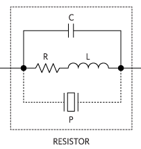
For resistors, you’ll also have to reckon with temperature dependence as well as the same range of piezoelectric and inductance characteristics that capacitors display. Worse, resistors can display variable resistance under higher voltages, and actually produce a small amount of random noise: Johnson Noise that depends on the value of the resistance.

Finally, the third article in the series tackles the PCB, summarizing a lot of potential manufacturing defects to look out for, as well as covering the parasitic capacitance, leakage currents, and frequency dependence that the actual fiberglass layers themselves can introduce into your circuit.

If you’re having a feeling of déjà-vu, the same series of articles ran in 2013 in Electronic Design but they’re good enough that we hope you won’t mind the redundant repetition all over again. And if you’re already quibbling with exactly what they mean by “passive”, we feel your pain: they’re really talking about parasitic effects, but we’ll let that slide too. We’re in a giving mood today.

[via Dangerous Prototypes]

Discussing Pulse-Width Modulation

[Michael Kleinigger] posted a lengthy discussion on Pulse-Width Modulation that goes beyond the traditional beginner tutorial. He starts a bit of background info on PWM and a tip about using a camera to judge frequency and duty cycle of LEDs. From there it’s down the rabbit hole with some testing of power-loss versus frequency.

When you change from frequencies of 50 Hz to 1 MHz how does the parasitic power loss from switching affect the overall efficiency of the circuit? It turns out there’s a rather large amount of loss at the highest level, around 1.5 mW. The greatest balance of low power loss and elimination of flicker seems to be right in the 300-500 Hz range.

Parasitic Power Devices


Aside from having a very cool name, parasitic power is an innovate way to recapture already spent power. This power can come in the form of wasted heating or cooling of a building for example. Last week the Southern Methodist University activated the first commercial Green Machine from ElectraTherm. The unit recycles residual heat from the building into electricity. So far, the 50kW Green Machine has exceeded expectations. The company also says owners can recoup the units cost after about three years.

Continue reading “Parasitic Power Devices”