[Dale Cook] has cats, and as he readily admits, cats are jerks. We’d use stronger language than that, but either way it became a significant impediment to making progress with an RFID-based sensor to allow his cats access to their litterbox. Luckily, though, he was able to salvage the project enough to give a great talk on RFID from first principles and learn about a potentially tragic mistake.
If you don’t have 20 minutes to spare for the video below, the quick summary is that [Dale]’s cats are each chipped with an RFID tag using the FDX-B protocol. He figured he’d be able to build a scanner to open the door to their playpen litterbox, but alas, the read range on the chip and the aforementioned attitude problems foiled that plan. He kept plugging away, though, to better understand RFID and the electronics that make it work.
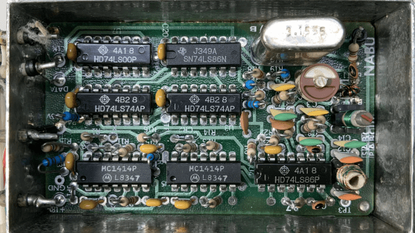
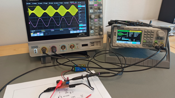
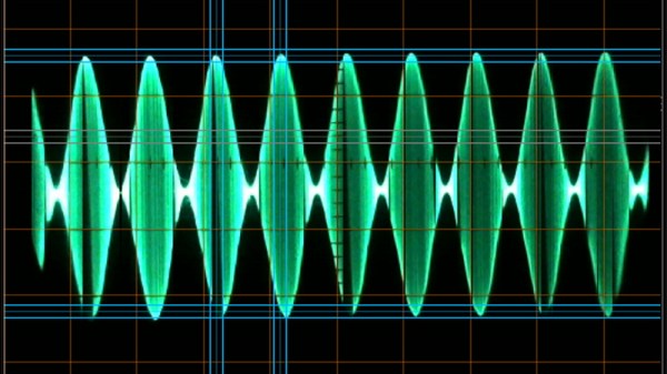
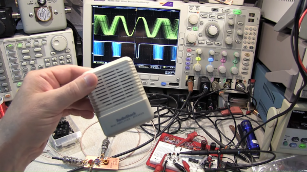
To that end, [Dale] rolled his own RFID reader pretty much from scratch. He used an Arduino to generate the 134.2-kHz clock signal for the FDX-B chips and to parse the returned data. In between, he built a push-pull driver for the antenna coil and an envelope detector to pull the modulated data off the carrier. He also added a low-pass filter and a comparator to clean up the signal into a nice square wave, which was fed into the Arduino to parse the Differential Manchester-encoded data.
Although he was able to read his cats’ chips with this setup, [Dale] admits it was a long road compared to just buying a Flipper Zero or visiting the vet. But it provided him a look under the covers of RFID, which is worth a lot all by itself. But more importantly, he also discovered that one cat had a chip that returned a code different than what was recorded in the national database. That could have resulted in heartache, and avoiding that is certainly worth the effort too.
Continue reading “RFID From First Principles And Saving A Cat”