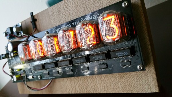
There’s something about Nixie Tube Clocks that keeps drawing hackers to build their own iterations, even if its been done a gazillion times before. Their depleting supply, and the high voltage drivers to control them, makes it all the more interesting. [Pete Mills], a veteran of several interesting projects, many of which we have featured here, is no exception and decided to build his own version of a Nixie Tube Clock, but with several nifty features.
To put it in a nut shell, his Clock uses Nixie tubes for display, has USB serial communication, temperature measurement, AC frequency measurement, time and date keeping with a software based RTC, software driven boost converter for the 175V DC nixie tube supply and a windows app for clock configuration.
The software based time keeping is pretty interesting. It is essentially a method to calibrate the crystal to more closely match real time, and some code to keep track of the time and date. This obviously leads to a reduction in components and the spin-offs that comes with that; increased reliability, cost reduction, real estate savings. The RTC code can easily be ported to other clock projects irrespective of the display used. Besides keeping track of time and date, it can also account for leap years, and report the day of the week. A zero-crossing detector connected to the low-voltage transformer supply that powers the clock can also be used as an alternative way of keeping time.
When connected to a serial console over UART, the clock can report back many variables depending on the queries it receives. The high voltage DC needed to drive the Nixie tubes is generated using a simple boost converter controlled by the micro controller. An important “gotcha” that [Pete] deduced after blowing off several fuses, was to disconnect the micro controller port connected to the PWM timer and explicitly set it to output low via software. There’s a couple of other issues that he ran into – such as board layout, power supply, incorrect pullups – that make for interesting reading. The clock enclosure is still work in progress, but [Pete] hopes to get it done sometime soon.
He also wrote a Windows application – Nixie Clock Communicator – to help with time setting and calibration. Finally, he describes in detail the process of calibrating the clock’s software based RTC. Based on his calculations, the clock will drift by about 48 seconds over an 8 month period. Since he will be adjusting for DST much sooner than that, his clock ought to be off from correct time by not more than a minute at any given time. Not bad for a clock that does not use a dedicated RTC chip. [Pete] still has some of the prototype boards to give away if someone is interested. If you’d rather build it yourself from scratch, [Pete] has posted the software code, schematics and PCB, and a BoM.


