
Never one to pass up the recycle pile at work, [Scott] usually doesn’t find much. A few old hard drives, maybe a ancient laptop every once in a while, but on very rare occasions he finds something actually useful. This latest haul is a gaggle of stepper motor drivers that, with a bit of work, can be reverse engineered and turned into an Arduino.
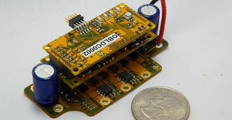
After prying into one of the plastic-enclosed boards, [Scott] found a LED, a quartet of transistors for powering the motor, and an ATMega168 microcontroller. Interestingly, most of the pins for the 168 were already broken out on the DA15 connector on each controller. The only thing needed was to build a programmer to dump the Arduino bootloader onto these little widgets.
After much trial and error (and building a new programming interface), [Scott] now has 100 Arduinos with a single stepper motor controller built in. He’s already made a toy light cycle rotate on a small stepper (after the break) and blink a LED, but with this many widgets, we’re wondering what crazy contraption [Scott] will come up with.
Continue reading “Dumpster Diving Nets 100 Arduino-powered Motor Controllers”