Quick Negative Voltage For An Op Amp

It is a classic problem when designing with op amps: you need the output to go to zero, but — for most op amps — you can’t quite get down to the supply rail. If your power options are a positive voltage and ground, you can’t get down to zero without a special kind of op amp which might not meet your needs. The best thing to do is provide a negative supply to the chip. Don’t have one? [Peter Demchenko] can help. He uses a simple two-transistor multivibrator along with some diodes and capacitors to generate a minimal negative voltage for this purpose.

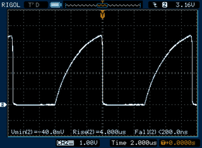
The circuit is simple and only produces a small negative voltage. He mentions that into a 910 ohm load, he sees about -0.3V. Not much, but enough to get that op amp down to zero with a reasonable load. Unlike other circuits he’s used in the past, this one is efficient. With a 5-volt input, it draws less than 1.5 mA.

Continue reading “Quick Negative Voltage For An Op Amp”

Negative Voltage Pushes AVR To New Heights

If we say that a hacker is somebody who looks at a “solved” problem and can still come up with multiple alternative solutions, then [Charles Ouweland] absolutely meets the grade. Not that we needed more evidence of his hacker cred given what we’ve seen from him before, but he recently wrote in to tell us about an interesting bit of problem solving which we think is a perfect example of the principle. He wanted to drive a salvaged seven segment LED display with an AVR microcontroller, but there was only one problem: the display needs 15V but the AVR is only capable of 5V. So what to do?
As it turns out, the first step to solving the problem was verifying there was actually a problem to begin with. [Charles] did some experimentation and found that the display didn’t actually need 15V to operate, and in fact would light up well enough at just 6.5V. This lowered the bar quite a bit, but it was still too high to power directly from the chip.

There were a few common ways to solve this problem, which no doubt the Hackaday reader is well aware of. But [Charles] wanted to take the path less traveled. More specifically, the path with the least amount of additional components he had to put on his PCB. He set out to find the absolute easiest way to make his 5V AVR light up a 6.5V LED, and ended up coming with a very clever solution that some may not even know is possible.

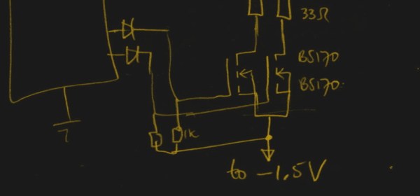
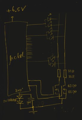
He reasoned that if he connected the source pins of two BS170 MOSFETs to a voltage of -1.5V, even when the AVR pin was 0V, they would be still be receiving 1.5V. This virtual “step ladder” meant that once the AVR’s pin goes high (5V), the relative voltage would actually be 6.5V and enough to drive his LEDs. Of course the only problem with that is that you need to have a source for -1.5V.

Getting a negative voltage would normally require adding more components to the design (which he set out to avoid in the first place), but then he came up with another clever idea. To pull the trick off, he actually feeds the AVR 6.5V, but raises the ground voltage by 1.5V with the addition of two 1N4007 diodes. This way the AVR gets a voltage within its capabilities and still can provide a relative 6.5V to the LEDs.

One might say [Charles] took the Kobayashi Maru approach, and simply redefined the rules of the game. But such is the power of the confounding negative voltage.

The Negative Rail Explained

With the high availability of modular components and incredible wealth of information and tutorials online, it’s now easier than ever for hackers and makers to assemble complex electronic projects without getting bogged down with the theory behind it all. But the downside is that the modern electronic hobbyist often doesn’t have as deep an understanding of the low-level concepts that they would have if they had to build everything from scratch. This can be a problem when they try diagnosing and repairing faults, or when they start to branch out into reverse engineering.

Which makes “Building Blocks” by [David Christensen] a very compelling series. Every week he will be demonstrating a new circuit on his blog, complete with a plain English explanation of how and why it’s used. In this first installment of the series, he’s tackling a concept most of us have seen when poking around in more complex electronic devices, but maybe never really gave much thought to: the negative rail.

What exactly is the negative rail, anyway? It’s pretty easy to understand the positive rail in a circuit and its relation to ground; even multiple positive rails, such as in devices which use both 5 V and 3.3 V, are simple enough to wrap your head around. Unfortunately when something drops below that logical 0V reference, it isn’t quite as intuitive. But as [David] explains, the negative rail in a circuit is critical for dealing with bipolar signals, such as audio, which ride above and below the 0 V center point.

[David] goes over a few methods used to create the negative rail, from the classic center-tap transformer to using a buck-boost converter. But not content with just describing how these circuits work, he walks the reader through the creation of a charge pump circuit that you can drop into your next project if you find yourself in need of the elusive voltage. After explaining and diagramming it, he builds the circuit on a scrap piece of copper clad board and puts it through some benchmarks to prove it matches the theory he laid out.

If you’re in the mood for more negative talk, check out the battle our very own [Steven Dufresne] had with voltages of varying polarity when building his BB-8 robot.