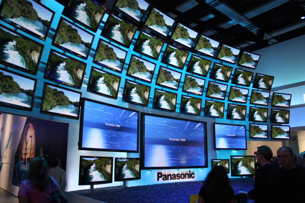
Exploring Turn Of The Century RAF Avionics

The second hand market is a wonderful thing; you never know what you might find selling for pennies on the dollar simply because it’s a few years behind the curve. You might even be able to scrounge up some electronics pulled out of a military aircraft during its last refit. That seems to be how [Adrian Smith] got his hands on a Control Display Unit (CDU) originally installed in a Royal Air Force AgustaWestland AW101 “Merlin” helicopter. Not content to just toss it up on a shelf, he decided to take a look inside of the heavy-duty cockpit module and see if he couldn’t make some sense out of how it works.

Unsurprisingly, [Adrian] wasn’t able to find much information on this device on the public Internet. The military are kind of funny like that. But a close look at the burn-in on the CDU’s orange-on-black plasma display seems to indicate it had something to do with the helicopter’s communication systems. Interestingly, even if the device isn’t strictly functional when outside of the aircraft, it does have a pretty comprehensive self-test and diagnostic system on-board. As you can see in the video after the break, there were several menus and test functions he was able to mess around with once it was powered up on the bench.

With the case cracked open, [Adrian] found three separate PCBs in addition to the display and keyboard panel on the face of the CDU. The first board is likely responsible for communicating with the helicopter’s internal systems, as it features a MIL-STD-1553B interface module, UART chips, and several RS-232/RS-485 transceivers. The second PCB has a 32-bit AMD microcontroller and appears to serve as the keyboard and display controller, possibly also providing the on-board user interface. The last board looks to be the brains of the operation, with a 25 MHz Motorola 68EC020 CPU and 1Mb of flash.

All of the hardware inside the CDU is pretty generic, but that’s probably the point. [Adrian] theorizes that the device serves as something of a generic pilot interface module, and when installed in the Merlin, could take on various functions based on whatever software was loaded onto it. He’s found pictures online that seem to show as many as three identical CDUs in the cockpit, all presumably running a different system.

[Adrian] has uncovered some interesting diagnostic information being dumped to the CDU’s rear connectors, but he’s still a long way off from actually putting the device to any sort of practical use. If any Hackaday readers have some inside information on this sort of hardware, we’re sure like to hear about it.

Continue reading “Exploring Turn Of The Century RAF Avionics”

Johnny Mnemonic, Broken Columns, And Pinball Repair

johnny

[Quinn Dunki] has come to realize the pinball machines of her youth aren’t the lame games she remembered. They’re actually quite marvelous in terms of electronics, mechanics, engineering and the all important hackability. Wanting to pick up a 90s dot matrix display pinball machine and being a [William Gibson] fan, [Quinn] picked up an old Johnny Mnemonic machine. She’s already looked into replacing the incandescent bulbs with LEDs, and has just wrapped up troubleshooting a broken plasma dot matrix display.

dots
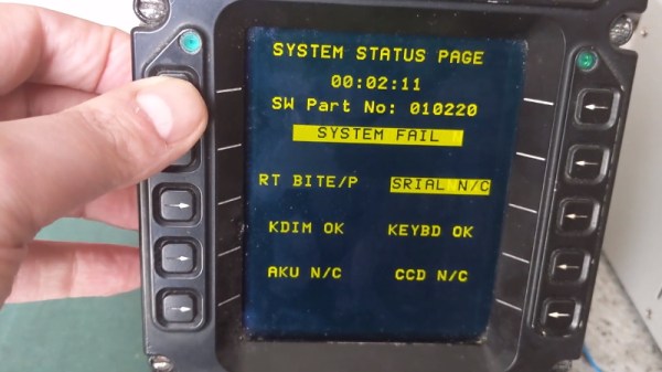
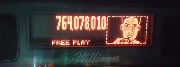
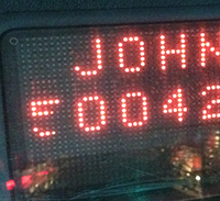
The neon dot matrix displays in pinball machines of this era are finicky devices with a lot of stuff that can go wrong. On powering the display up, [Quinn] noticed a few columns on the left side of the display weren’t working. These machines have great diagnostic menus, so running a test that displays a single column at a time revealed two broken columns. However, when a solid fill test was run, all the columns work, save for a few dots in the upper left corner. This is an odd problem to troubleshoot, but after more tests [Quinn] realized dots in column five and six only work iff both adjacent dots in the same row are lit.

The power supply seemed okay, leaving the problem to either a logic problem, or something wrong in the glass. With a meter, [Quinn] deduced there was a short between the two broken columns, and tracing every thing out revealed a problem in the hermetically sealed display filled with noble gasses. A replacement display was ordered.

While [Quinn] was replacing the display, she decided it would be a good time to rehab the almost-but-not-quite out of spec driver board for the display. The power resistors had scorched the PCB, but didn’t damage any traces. Replacing the parts with modern components with a higher power rating brought the board back to spec with components that should last longer than the 20-year-old parts previously inhabiting the driver board.

It was a lot of effort, but now [Quinn] has a brand new display for her pinball machine and is ready to move on to the next phase of her restoration.

Reverse Engineering A Plasma Dot Matrix Display

A while back, [DragonMinded] picked up a bunch of old arcade and pinball parts from a guy on Craigslist. These parts sat around for a while until a really neat plasma dot matrix display was found in the corner of a box in his garage. Doing the only reasonable thing, [DragonMinded] figured out how to interface this ancient display with a microcontroller.

After extensive Internet research on his display, [DragonMinded] could only find a one page datasheet for his APD-128G064A-1 display. Luckily, this datasheet had voltage requirements, and since the display only had six input pins he could probe the circuit to see what goes where.

After generating a crude schematic, [DragonMinded] prototyped a driver circuit with an Arduino. When the function of each pin was discovered, the Arduino libraries were discarded and replaced with raw register access.

It was a fair amount of work, but [DragonMinded] eventually got to the point where he could draw anything he wanted on the screen. Next on the to-do list is turning it into a terminal or Twitter machine, as with all good display hacks.