Repairing A Couple Of Very Expensive Registered DDR5 RAM Sticks

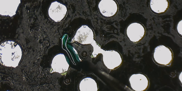
It’s definitely a sign of the times when repair shops get handed sticks of registered ECC DDR5 RAM by businesses to try and fix, rather than just tossing the defective ones and slotting in a fresh bunch. This is how [northwestrepair] ended up with two of these ECC RDIMMs, with a current market valuation of a rather nice budget car.
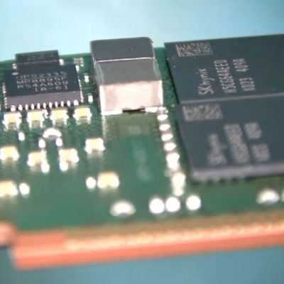
The 128 GB stick was first on the bench, with the fault being that it would fail DDR5 training on boot. This suggests that one or more of the DRAM BGA packages had developed a cracked solder joint, which is something that you could conceivably fix with more diagnosing and testing for a single IC reballing.

In this case doing a reflow cycle was enough to bring the RAM back to life, with the DDR5 training now passing without issues in a test system.

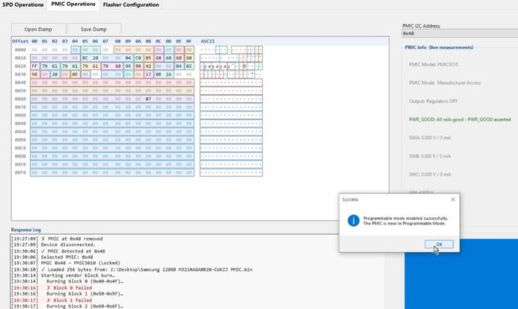
For the 256 GB stick things wouldn’t be so easy, as it seemed completely dead. This suggested a dead PMIC, as this is the component on DDR5 RAM responsible for ensuring that the DRAM ICs even power on. The SPD ROM was another option, so that got swapped first, which does require reprogramming the RDIMM. For this the earlier SPD dump image was reflashed, but swapping this chip made no difference.

After some additional reflowing of a few suspect ICs, still nothing happened. Following this a lot of reballing and other troubleshooting steps followed, only for the problem to be one shorted MLCC and a broken PMIC, potentially caused by whoever dropped said RDIMM onto the server room floor.

Cracked MLCCs do appear to be a very common cause of failures, as they’re often used as filter capacitors, same as for this RDIMM. Checking for shorts across a number of such MLCCs can be a good way to shorten a diagnostic cycle. Since this RDIMM was dropped, reballing every IC probably was still a good move as this may have cracked some solder balls.

Continue reading “Repairing A Couple Of Very Expensive Registered DDR5 RAM Sticks” →
Laptop GPU Upgrade With Just A Little Reballing

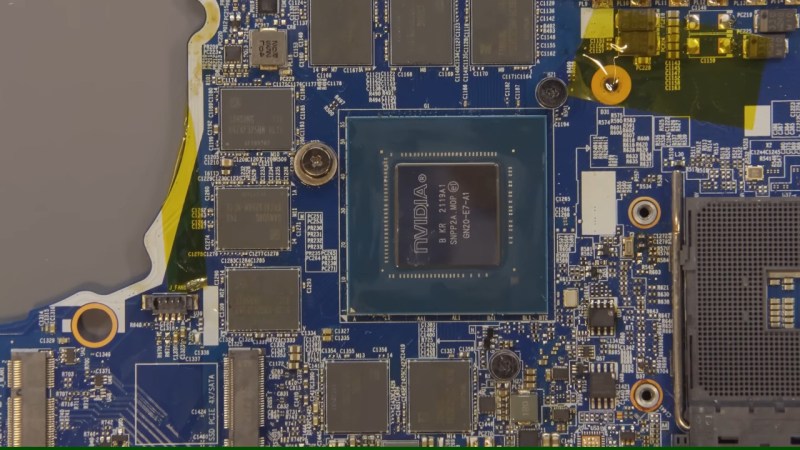
Modern gaming laptops are in an uncomfortable spot – often too underpowered for newest titles, but too bulky to be genuinely portable. It doesn’t help they’re not often upgradeable, so you’re stuck with what you’ve bought – unless, say, you’re a hacker equipped some tools for PCB reflow? If that’s the case, welcome to [TechModLab]’s video showing you the process of upgrading a laptop’s soldered-on NVIDIA GPU, replacing the 3070 chip with a 3080.

You don’t need much – the most exotic tool is a BGA rework station, holding the mainboard steady&stiff and heating a specific large chip on the board with an infrared lamp from above. This one is definitely a specialty tool, but we’ve seen hackers build their own. From there, some general soldering tools like flux and solder wick, a stencil for your chip, BGA balls, and a $20 USB-C hotplate are instrumental for reballing chips – tools you ought to have.

Reballing was perhaps the hardest step of the journey – instrumental for preparing the GPU before the transplant. Afterwards, only a few steps were needed – poking a BGA ball that didn’t connect, changing board straps to adjust for the new VRAM our enterprising hacker added alongside the upgrade, and playing with the driver process install a little. Use this method to upgrade from a lower-end binned GPU you’re stuck with, or perhaps to repair your laptop if artifacts start appearing – it’s a worthwhile reminder about methods that laptop repair shops use on the daily.

Itching to learn more about BGAs? You absolutely should read this article series by our own [Robin Kearey]. We’ve mostly seen reballing used for upgrading RAM on laptop and Raspberry Pi boards, but seeing it being used for an entire laptop is nice – it’s the same technique, just scaled up, and you always can start by practicing at a smaller scale. Now, it might feel like we’ve left the era of upgradable GPUs on laptops, and today’s project might not necessarily help your worries – but the Framework 16 definitely bucks the trend.

Continue reading “Laptop GPU Upgrade With Just A Little Reballing” →

Scotty Allen Builds A USB Drive From An IPhone

What happens when you come across a mysterious, partially populated circuit board in the Huaqiangbei electronics market in Shenzhen? If you’re [Scotty Allen], the only answer is to make your own USB drive from iPhone parts.

[Scotty] made a name for himself through his YouTube channel Strange Parts where he built his own iPhone from scratch, added a headphone jack to an iPhone, and other various exploits involving hot air in Shenzhen. This latest build is no different. It begins with a random PCB [Scotty] found at the electronics market. It has a USB port on one end, it has pads for an iPhone memory chip, and it has an IC that looks like a USB to Flash converter.

The build involved finding a few broken iPhones, desoldering and reballing their Flash chips, and when those didn’t work, finding the correct Flash chips for this tiny little USB adapter board. Here, [Scotty] ran into trouble. The first Flash chip didn’t have the right pins, there was blue smoke, and the toolchain for initializing the USB to Flash IC was a mess.

In the end, [Scotty] managed to create a USB Flash drive after five or six visits to the electronics market, two stencils to reball Flash chips, and finding the OEM software for the USB to Flash chip on this very special PCB. That, itself, required Windows (the horror!), and finding the right version of the software.

Is this technically building a Flash drive purely from disposed iPhone components? We’d quibble. But is it a cool build, regardless? Absolutely. And the real story here is how quickly [Scotty] could iterate on his engineering. When the greatest electronics market is right around the corner, you can do anything with a microscope and a hot air gun.