My introduction to electronic manufacturing was as a production technician at Pennsylvania Scale Company in Leola PA in the early 1980’s. I learned that to work on what I wanted to work on I had to get my assigned duties done by noon or thereabouts. The most important lesson I had learned as a TV repairman, other than not to chew on the high voltage cable, was to use your eyes first. I would take a box of bad PCB’s that were essentially 6502 based computers that could count and weigh, and first go through inspecting them; usually the contents were reduced 50% right off by doing this. Then it was a race to identify and fix the remaining units and to keep my pace up I had to do my own desoldering.
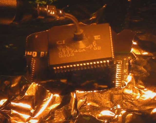
It worked like this; you could set units aside with instructions and the production people would at some point go through changing components etc. for you or you could desolder yourself. I was pretty good at hand de-soldering 28 and 40 pin chips using a venerable Soldapulit manual solder sucker (as they were known). But to really cook I would wait for a moment when the production de-soldering machine was available. There was one simple rule for using the desoldering station: clean it when done! Failure to do so would result in your access to the station being suspended and then you might also incur the “wrath of production” which was not limited to your lunch bag being found frozen solid or your chair soaked in defluxing chemicals.
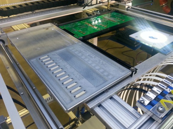 Pick and Place machines are one of the double-edged swords of electronics.They build your boards fast, but if you don’t have everything setup perfectly, they’ll quickly make a mess. A pick and place can’t grab a resistor from a pile and place it – so far only humans can pull that one off. They need parts organized and oriented in reels or trays.
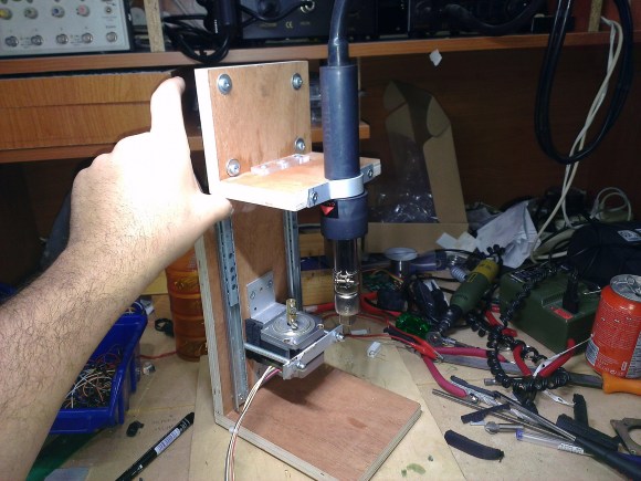
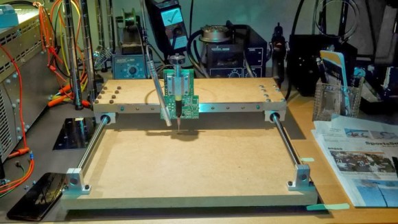 Populating a large surface mount PCB can take forever. [craftycoder] from Freeside Atlanta has built a great looking