Making An Audio Spectrum Analyzer With A Microcontroller

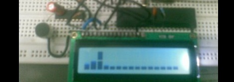
While [Vinod] says he’s not an expert in this sort of thing, we really like his audio spectrum analyzer build from a simple microcontroller and LCD display.

It is a well-studied fact that every audio waveform – a recording of your voice, for instance – is just the sum of many, many sine waves. These sine waves can be plucked out using Fourier analysis, using a Discrete Fourier transform. This is the principle that spectrum analyzers operate under; [Vinod] wrote a bit of code using DFT to take apart audio captured from a microphone and output their frequency on an LCD display.

To output the spectrum on his LCD, [Vinod] stacked horizontal bars up into 8 custom characters in his display. Like [Vinod]’s previous audio on an ATMega32 experiment, an LM324 amplifier is connected to the ATMega through an analog pin. [Vinod] has a very clever build on his hands with his spectrum analyzer, and a great answer to the perennial ‘how do I build a guitar tuner’ questions we’re constantly asked.

After the break, you can see [Vinod]’s spectrum analyzer in action. Be forewarned; you may want to turn down the volume.

Continue reading “Making An Audio Spectrum Analyzer With A Microcontroller”

Adding Visuals To Chiptune Performances

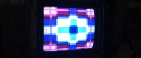
If you’ve never been to a chiptune show – yes, they exist – you’ve noticed the awesome visuals behind the performers that are usually displayed with a glitching NES. If it’s a really good show, that 8-bit visualization will be in sync with the music and may actually serve as a lo-fi spectrum analyzer. [Andy] came up with his own visualization system for a Sega Genesis or Megadrive. With 16 bits behind his build, we’ll say if far surpasses the lowly NES.

For his visualization, [Andy] feeds audio into an ATMega328 and the ever-popular MSGEQ7 seven-band graphic equalizer IC. The output from the EQ goes straight to the second controller input of a Sega Nomad [Andy] had lying around that is running a custom ROM for his show. The ROM is programmed in tandem with the microcontroller project to serve as a spectrum analyzer for his shows.

You can check out [Andy]’s visualization with the chiptunes of Danimal Cannon after the break. We would prefer a demo featuring An0vA and the code for the microcontroller, but it’s still a very nice demo indeed.

Continue reading “Adding Visuals To Chiptune Performances”

Character LCD Spectrum Analyzer Made Simple With A Dedicated IC

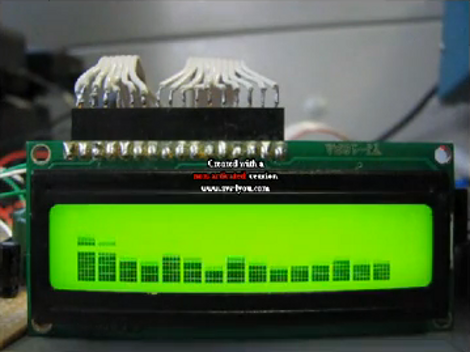
[El Artis] just finished building an audio spectrum analyzer that uses a character LCD. The uses an Arduino to drive the display, but unlike other meters that use the microcontroller for analysis, [El Artis] is using a discrete IC for that task.

This project uses the MSGEQ7 graphic equilizer display filter chip to grab frequency data from the audio source. The chip connects to your microcontroller of choice using two digital pins and one analog pin. [El Artis] points us to [J Skoba’s] post about how to use it with an Arduino, then adds his own custom character routines for an HD44780 display. You’ll notice that there are sixteen bars in the image above, which conflicts with the 7 outputs the chip offers. [El Artis] averages neighboring values in order to add the extra outputs.

Don’t miss the demo video after the break. If you’re looking to use this part in one of your projects, we noticed they’re a little hard to find (octopart doesn’t return any suppliers) but SparkFun has them.

Continue reading “Character LCD Spectrum Analyzer Made Simple With A Dedicated IC”

Spectrum Analyzer Users Custom Characters On An HD44780 Display

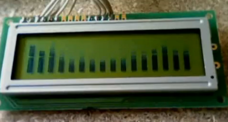
[Camilo] built a spectrum analyzer to use with his audio system (translate). The hardware is quite simple, using an op-amp, microcontroller and LCD display. He chose an LMV324M low-voltage op-amp which connects to the incoming audio signal and feeds its output to the microcontroller’s ADC. In this case, he chose a Freescale microcontroller from the HCS08 family which is running at 20 MHz. This gives the project enough speed to properly analyze the incoming audio. He mentions that he’s following the guidelines set forth in the Nyquist-Shannon sampling theorem and using the Fast Fourier Transform when processing the samples.

This isn’t the first time we’ve seen a character LCD used as a display for a frequency analyzer. This other ATmega8-based rendition supported several different screen layouts. These displays have enough RAM to store eight custom characters. Each character is 5×8 pixels, lending eight levels to each character for a total of 16 for each column seen above. We love the simplicity of the hardware in the project but we wouldn’t mind seeing an additional potentiometer to fine-tune how the data is displayed on the screen to take advantage of its full range. See the project in action in the clip after the break.

Continue reading “Spectrum Analyzer Users Custom Characters On An HD44780 Display”

Arduino Powered 2.4 GHz Spectrum Analyzer

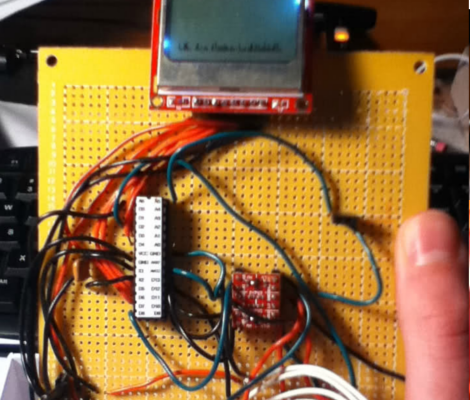
[Fred] dropped a note in our tip line to let us know about arduino forum user [bilbo]’s latest project: A 3-in-one spectrum analyzer, oscilloscope, volt-meter combo. The build consists of an Arduino, radio board and Nokia 5110 LCD breakout board.  The (thin) video after the jump shows the rig in action. Though soldered to a full sized perf-board we can see later, smaller, battery powered versions prove useful in rooting out wayward bluetooth signals, or just finding that lost microwave oven. Although [bilbo] uses the same radio board as similar builds  his creation boasts several different display modes, as well as doubling as a volt meter and miniature-oscilloscope. There is no shortage of previous spectrum analyzer builds, but this one is the first one we have seen running on an Arduino.

Thanks for the tip [Fred]! If you feel like wedging some frequency scanning capabilities into your next project don’t forget to check out [bilbo]’s forum posts for source code!

Continue reading “Arduino Powered 2.4 GHz Spectrum Analyzer”

Building A Better Spectrum Analyzer For Radio Enthusiasts

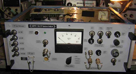
This spectrum analyzer project seeks to improve the quality of tools available to amateur radio operators. A lot of thought has gone into the design, and those details are shared in the verbose project log. The case was originally a CATV link transmitter, but most of the controls seen above have been added for this build, with unused holes filled and finished to achieve the clean look.

One noteworthy part of the build is the time that went into building a rather complicated-looking 1013.3 MHz cavity bandpass filter. Despite the effort, the filter didn’t work. Details are a bit sketchy but it seems that some additional tuning brought it within spec to complete that portion of the device.

This certainly makes other toy spectrum analyzers look like… toys.

[Thanks William]

PIC Spectrum Analyzer Uses Fast Fourier Transform Routine

[Simon Inns] just rolled out his latest project, a PIC based spectrum analyzer. He’s using a Fast Fourier Transform routine crafted in C to run as efficiently as possible on the 8-bit chip. The video after the break shows that the results are quite pleasing, with just a bit of noticeable lag between the sound and the waveform representation on the graphic LCD. We found his notes about using an audio amplifier chip to be interesting. He utilizes the properties of an LM386 to move the input signals from a range of -0.5V to +0.5V into a very ADC friendly range of 0-5V.

Continue reading “PIC Spectrum Analyzer Uses Fast Fourier Transform Routine”