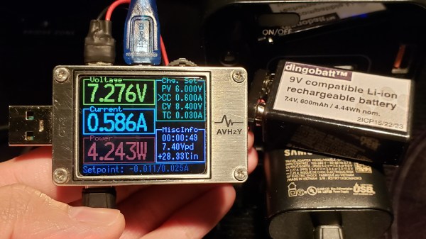
Showing a USB-C tester running the DingoCharge script, charging a battery pack at 7V. To the right is a battery pack being charged, and a USB-C charger doing the charging.

Use USB-C Chargers To Top Up Li-Ion Packs With This Hack

In USB-C Power Delivery (PD) standard, the PPS (Programmable Power Supply) mode is an optional mode that lets you request a non-standard voltage from a charger, with the ability to set a current limit of your choice, too. Having learned this, [Jason] from [Rip It Apart] decided to investigate — could this feature be used for charging Li-Ion battery packs, which need the voltage and current to vary in a specific way throughout the charging process? Turns out, the answer is a resounding “yes”, and thanks to a USB-C tester that’s programmable using Lua scripts, [Jason] shows us how we can use a PPS-capable USB-C charger for topping up our Li-Ion battery packs, in a project named DingoCharge.

The wonderful write-up answers every question you have, starting with a safety disclaimer, and going through everything you might want to know. The GitHub repo hosts not only code but also full installation and usage instructions.

DingoCharge handles more than just Li-Ion batteries — this ought to work with LiFePO4 and lithium titanate batteries, too.  [Jason] has been working on Ni-MH and lead-acid support. You can even connect an analog output thermal sensor and have the tester limit the charge process depending on the temperature, showing just how fully-featured a solution the DingoCharge project is.

The amount of effort put into polishing this project is impressive, and now it’s out there for us to take advantage of; all you need is a PPS-capable PSU and a supported USB-C tester. If your charger’s PPS is limited by 11V, as many are, you’ll only be able to fully charge 2S packs with it – that said, this is a marked improvement over many Li-Ion solutions we’ve seen. Don’t have a Li-Ion pack? Build one out of smartphone cells! Make sure your pack has a balancing circuit, of course, since this charger can’t provide any, and all will be good. Still looking to get into Li-Ion batteries? We have a three-part guide, from basics to mechanics and electronics!

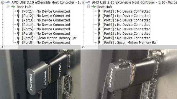
Showing the same thumbdrive plugged into the same USB-C port in two different orientations, enumerating as two different USB ports

Dirty USB-C Tricks: One Port For The Price Of Two

[RichardG] has noticed a weird discrepancy – his Ryzen mainboard ought to have had fourteen USB3 ports, but somehow, only exposed thirteen of them. Unlike other mainboards in this lineup, it also happens to have a USB-C port among these thirteen ports. These two things wouldn’t be related in any way, would they? Turns out, they are, and [RichardG] shows us a dirty USB-C trick that manufacturers pull on us for an unknown reason.

On a USB-C port using USB3, the USB3 TX and RX signals have to be routed to two different pin groups, depending on the plugged-in cable orientation. In a proper design, you would have a multiplexer chip detecting cable orientation, and routing the pins to one or the other. Turns out, quite a few manufacturers are choosing to wire up two separate ports to the USB-C connector instead.

In the extensive writeup on this problem, [Richard] explains how the USB-C port ought to be wired, how it’s wired instead, shows telltale signs of such a trick, and how to check if a USB-C port on your PC is miswired in the same way. He also ponders on whether this is compliant with the USB-C specification, but can’t quite find an answer. There’s a surprising amount of products and adapters doing this exact thing, too, all of them desktop PC accessories – perhaps, you bought a device with such a USB-C port and don’t know it.

As a conclusion, he debates making an adapter to break the stolen USB3 port out. This wouldn’t be the first time we’re cheated when it comes to USB ports – the USB2 devices with blue connectors come to mind.

An “unbusy” USB-C Port Doubles-up For JTAG Programming

Board space is a premium on small circuit board designs, and [Alvaro] knows it. So instead of adding a separate programming port, he’s found a niche USB-C feature that lets him use the port that he’s already added both for its primary application and for programming the target microcontroller over JTAG. The result is that he no longer needs to worry about spending precious board space for a tiny programming port; the USB-C port timeshares for both!

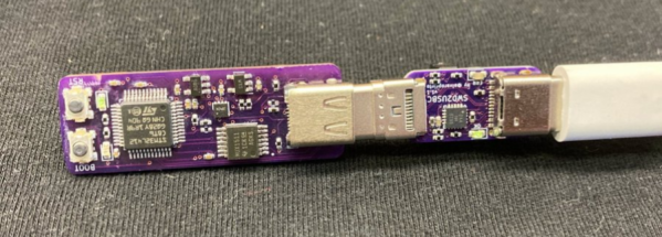
In a Twitter thread (Unrolled Link), [Alvaro] walks us through his discovery and progress towards an encapsulated solution. It turns out that the USB-C spec supports a “Debug-Accessory Mode” specification, where some pins are allowed to be repurposed if pins CC1 and CC2 are pulled up to Logic-1. Under these circumstances, the pin functions are released, and a JTAG programmer can step in to borrow them. To expose the port to a programmer, [Alvaro] cooked up a small breakout board with a USB-C plug and separate microcontroller populated on it.

This board also handles a small quirk. Since [Alvaro’s] choice of programming pins aren’t reversible, the USB-C plug will only work one of the two ways it can be plugged in. To keep the user informed, this breakout board sports a red LED for incorrect orientation and a green LED for correct orientation–nifty. While this design quirk sacrifices reversibility, it preserves the USB 2.0 D+ and D- pins while also handling some edge cases with regard to the negotiating for access to the port.

Stick through [Alvaro]’s Twitter thread for progress pics and more details on his rationale behind his pin choices. Who knows? With more eyes on the USB-C feature, maybe we’ll see this sort of programming interface become the norm?

[Alvaro] is no stranger to Hackaday. In fact, take a tour back to our very first Supercon to see him chat about shooting lasers at moving targets to score points on a DEFCON challenge in the past