Raspberry Pi biosensor with screen-printed electrodes

Raspberry Pi And PpLOGGER Make A Low-Cost Chemiluminescence Detector

[Laena] and her colleagues at the La Trobe Institute for Molecular Science in Melbourne, Australia used a Raspberry Pi to make a low-cost electrochemiluminescence (ECL) detector to measure inflammation markers, which could be used to detect cardiovascular disease or sepsis early enough to give doctors a better chance at saving a patient’s life.

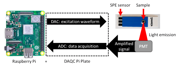
ECL reactions emit light as a result of an electrically-activated chemical reaction, making them very useful for detecting biochemical markers in blood, saliva, or other biological samples.  ECL setups are fundamentally fairly straightforward. The device includes a voltage reference generator to initiate the chemical reaction and a photomultiplier tube (PMT) to measure the emitted light. The PMT outputs a current which is then converted to a voltage using a transimpedance amplifier (TIA). That signal is then sampled by the DAQCplate expansion board and the live output can be viewed in ppLOGGER in real-time.

Using the RPi allowed the team to do some necessary, but pretty simple signal processing, like converting the TIA voltage back to a photocurrent and integrating the current to obtain the ECL intensities. They mention the added signal processing potential of the RPi was a huge advantage of their setup over similar devices, however, simple integration can be done pretty easily on most any microcontroller. Naturally, they compared their device to a standard ECL setup and found that the results were fairly comparable between the two instruments. Their custom device showed a slightly lower limit of detection than the standard setup.

Their device costs roughly $1756 USD in non-bulk quantities with the PMT being the majority of the cost ($1500). Even at almost $2000, their device provides more than $8000 in savings compared to ECL instruments on the market. Though cost is much more than just the bill of materials, we like seeing the community making efforts to democratize science, and [Laena] and her colleagues did just that. I wonder if they can help us figure out the venus fly trap while they’re at it?

Showing the same thumbdrive plugged into the same USB-C port in two different orientations, enumerating as two different USB ports

Dirty USB-C Tricks: One Port For The Price Of Two

[RichardG] has noticed a weird discrepancy – his Ryzen mainboard ought to have had fourteen USB3 ports, but somehow, only exposed thirteen of them. Unlike other mainboards in this lineup, it also happens to have a USB-C port among these thirteen ports. These two things wouldn’t be related in any way, would they? Turns out, they are, and [RichardG] shows us a dirty USB-C trick that manufacturers pull on us for an unknown reason.

On a USB-C port using USB3, the USB3 TX and RX signals have to be routed to two different pin groups, depending on the plugged-in cable orientation. In a proper design, you would have a multiplexer chip detecting cable orientation, and routing the pins to one or the other. Turns out, quite a few manufacturers are choosing to wire up two separate ports to the USB-C connector instead.

In the extensive writeup on this problem, [Richard] explains how the USB-C port ought to be wired, how it’s wired instead, shows telltale signs of such a trick, and how to check if a USB-C port on your PC is miswired in the same way. He also ponders on whether this is compliant with the USB-C specification, but can’t quite find an answer. There’s a surprising amount of products and adapters doing this exact thing, too, all of them desktop PC accessories – perhaps, you bought a device with such a USB-C port and don’t know it.

As a conclusion, he debates making an adapter to break the stolen USB3 port out. This wouldn’t be the first time we’re cheated when it comes to USB ports – the USB2 devices with blue connectors come to mind.

Get To Know Touch With This Dev Board

In the catalogue of the Chinese parts supplier LCSC can be found many parts not available from American or European suppliers, and thus anyone who wants to evaluate them can find themselves at a disadvantage. [Sleepy Pony Labs] had just such a part catch their eye, the Sam&Wing AI08 8 channel capacitive touch controller. How to evaluate a chip with little information? Design a dev board, of course!

The chip tested is part of a family all providing similar functionality, but with a variety of interface options. The part tested has eight touch inputs and a BCD output. Said output is used to feed a 74 series decoder chip and drive some LEDs. The touch pads were designed with reference to a Microchip application note which incidentally makes for fascinating reading on the subject as it covers far more than just simple touch buttons.

Whether or not you’ll need this touch chip is a matter for your own designs, however, what this project demonstrates is that with the ready availability of cheap custom PCBs and unexpected parts it’s not beyond reason to create boards just for evaluation purposes.

Perhaps the subject of a previous Hackaday piece would have found this board useful.

KiCad 2022 Year End Recap

KiCad 2022 End-of-Year Recap And 7.0 Preview

[Chris Gammell] moderated the KiCad 2022 End-of-Year Recap with several KiCad developers and librarians. They reviewed what’s been bubbling up in the nightly KiCad 6 builds, what we can expect from KiCad 7, and even answered some questions from the user community. Over the course of 2022, the KiCad project has grown both its development team and library team. The project even has a preliminary support commitment from the CERN Drawing Office!

Improvements to the KiCad Schematic Editor include smart wire dragging that simplifies moving components around within schematic diagrams. Components selected in the schematic now remain selected while switching to the PCB Editor. Internal documentation of schematics has advanced with support for fonts, embedded graphics, and the inclusion of hypertext links to datasheets and other reference materials. New features for PDF generation offer interactive files and links between sheets.

A new search panel within the KiCad PCB Editor supports finding components by footprint, net, or text search. A property panel allows common properties to be edited across multiple selected items. While a full-blown auto-router remains outside of the scope for KiCad, “push and shove” routing is faster and easier. An “attempt to finish” feature routes a quick connection for the currently selected trace, and “pack and move” positions all selected footprints into proximity to simplify placing them as neighbors within the board layout.

The KiCad PCB Editor also adds support for the use of fonts and inverted “knockout text” which even works on copper zones. Bitmap graphics can be imported and scaled beneath layout work as reference illustrations. Private footprint layers can be used to place extra documentation within footprints. The design rule checker (DRC) now can catch more layout issues, especially those that may impact manufacturability.

These are just a sampling of the impressive improvements we can expect with KiCad 7.0. There are also additions to circuit simulation and modeling features, a new command line interface for script-based automation, ARM64 support for KiCad running on Apple silicon, and a huge number of additions to the default library including symbols, footprints, and 3D Viewer models.

The KiCad team suggests several ways to support the project. There are always needs for additional developers and librarians. Financial contributions can be made at kicad.org. As users, we can run the nightly builds, try to break them, and give feedback in the form of detailed bug reports. Community testing will help make KiCad 7.0 as solid as possible. The project team is also seeking open hardware projects to include with KiCad 7.0 as demos.  For example, the StickHub project was included with KiCad 6.0 as a demo.

The official release of KiCad 7.0 is currently scheduled for January 31, 2023. While we wait, let’s flashback to our January 2022 presentation of what features made it into the KiCad 6.0 release.

Continue reading “KiCad 2022 End-of-Year Recap And 7.0 Preview”

Fritzing diagram of connections between the Wemos D1 board, the TP4056 board, the pushbutton and the LiIon battery

Battery-Powered ESP8266 Sensor? Never Been Simpler

Say, you’re starting your electronics journey with a few projects in mind. You have an ESP8266 board like the Wemos D1, a Li-Ion battery, you want to build a small battery-powered sensor that wakes up every few minutes to do something, and you don’t want to delve into hardware too much for now. Well then, does [Mads Chr. Olesen] have a tutorial for you! Here, you’ll learn the quick and easy way to get your sensor up and running, learn a few tricks for doing sleep Arduino environment, and even calculate how long your specific battery could last. Continue reading “Battery-Powered ESP8266 Sensor? Never Been Simpler”

In Praise Of “Just Because” Hacks

Sometimes you pick a project because the world needs it to be done. Or maybe you or a friend need it. Or maybe you don’t really need it, but it fulfills a longstanding dream. In my mind, the last stop before you reach “why am I doing this” is the “just because” hack.

The ideal “just because” hack is limited in scope. You don’t want to spend years on a whimsical project, and because of this a “just because” hack isn’t usually motivating enough to keep you going that long anyway, except for the tenacious few. A “just because” doesn’t necessarily have to be an easy win, but it makes sense for you to see your way out before you get in too deep.

I’m not sure if it’s the Baader-Meinhof phenomenon or not, but in the last week or so in the Hackaday universe, a lot of people have been singing the praises of “just because” hacks. (Check out this one discussion, for instance.) Mostly, it’s a combination of them turning out better than initially thought, or it’s about the learning that came along for the ride. Of course, many of them spin off into longer, serious projects even if they didn’t start that way.

Not everything in life can be frivolous, of course. But that makes the “just because” hack that much sweeter, and you should try to make mental room for them if you can. When the stakes are low, creativity can be high. You might still want to impose a deadline, lest you fall into eternal yak shaving, but take it easy. You don’t need a justification all the time: the journey can be the destination.

a Pi Pico on a breadboard, running a 7-segment counter gateware, with a 7-segment digit and a pushbutton next to the Pico

Want To Play With FPGAs? Use Your Pico!

Ever want to play with an FPGA, but don’t have the hardware? Now, if you have one of those ever-abundant Pi Picos, you can start playing with Verilog without getting an FPGA board. The FakePGA project by [tvlad1234], based on the Verilator toolkit, provides you with a way to compile Verilog into C++ for the RP2040. FakePGA even integrates RP2040 GPIOs so that they work as digital pins for the simulated GPIOs, making it a significant step up from computer-aided FPGA code simulation

[tvlad1234] provides instructions for setting this up with Linux – Windows, though untested, could theoretically run this through WSL. Maximum clock speed is 5KHz – not much, but way better than not having any hardware to test with. Everything you’d want is in the GitHub repo – setup instructions, Verilog code requirements, and a few configuration caveats to keep in mind.

We cover a lot of projects where FPGAs are used to emulate hardware of various kinds, from ISA cards to an entire Game BoyCPU emulation on FPGAs is basically the norm — it’s just something easy to do with the kind of power that an FPGA provides. Having emulation in the opposite direction is unusual,  though, we’ve seen FPGAs being emulated with FPGAs, so perhaps it was inevitable after all. Of course, if you have neither a Pico nor an FPGA, there’s always browser based emulators.

Continue reading “Want To Play With FPGAs? Use Your Pico!”