All About USB-C: High-Speed Interfaces

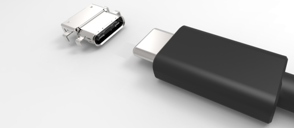
One amazing thing about USB-C is its high-speed capabilities. The pinout gives you four high-speed differential pairs and a few more lower-speed pairs, which let you pump giant amounts of data through a connector smaller than a cent coin. Not all devices take advantage of this capability, and they’re not required to – USB-C is designed to be accessible for every portable device under the sun. When you have a device with high-speed needs exposed through USB-C, however, it’s glorious just how much USB-C can give you, and how well it can work.

The ability to get a high-speed interface out of USB-C is called an Alternate Mode, “altmode” for short. The three altmodes you can encounter nowadays are USB3, DisplayPort and Thunderbolt, there’s a few that have faded into obscurity like HDMI and VirtualLink, and some are up and coming like USB4. Most altmodes require digital USB-C communication, using a certain kind of messages over the PD channel. That said, not all of them do – the USB3 is the simplest one. Let’s go through what makes an altmode tick. Continue reading “All About USB-C: High-Speed Interfaces”

Showing the same thumbdrive plugged into the same USB-C port in two different orientations, enumerating as two different USB ports

Dirty USB-C Tricks: One Port For The Price Of Two

[RichardG] has noticed a weird discrepancy – his Ryzen mainboard ought to have had fourteen USB3 ports, but somehow, only exposed thirteen of them. Unlike other mainboards in this lineup, it also happens to have a USB-C port among these thirteen ports. These two things wouldn’t be related in any way, would they? Turns out, they are, and [RichardG] shows us a dirty USB-C trick that manufacturers pull on us for an unknown reason.

On a USB-C port using USB3, the USB3 TX and RX signals have to be routed to two different pin groups, depending on the plugged-in cable orientation. In a proper design, you would have a multiplexer chip detecting cable orientation, and routing the pins to one or the other. Turns out, quite a few manufacturers are choosing to wire up two separate ports to the USB-C connector instead.

In the extensive writeup on this problem, [Richard] explains how the USB-C port ought to be wired, how it’s wired instead, shows telltale signs of such a trick, and how to check if a USB-C port on your PC is miswired in the same way. He also ponders on whether this is compliant with the USB-C specification, but can’t quite find an answer. There’s a surprising amount of products and adapters doing this exact thing, too, all of them desktop PC accessories – perhaps, you bought a device with such a USB-C port and don’t know it.

As a conclusion, he debates making an adapter to break the stolen USB3 port out. This wouldn’t be the first time we’re cheated when it comes to USB ports – the USB2 devices with blue connectors come to mind.

Top side of the VL670 breakout board, with two USB connectors and the VL670 chip in the center.

A Chip To Bridge The USB 2 – USB 3 Divide

On Twitter, [whitequark] has  found and highlighted an intriguing design – a breakout board for the VL670, accompanied by an extensive yet very easy to digest write-up about its usefulness and inner workings. The VL670 is a chip that addresses a surprising problem – converting USB 2.0 signals into USB 3.0.

If you have a USB 2.0 device and a host with only USB 3.0 signals available, this chip is for you. It might be puzzling – why is this even needed? It’s about the little-known dark secret of USB3, that anyone can deduce if they ever have to deal with a 9-pin USB 3.0 connector where one of the three differential pairs doesn’t quite make contact.

When you see a blue “3.0” port, it’s actually USB 2 and USB 3 — two separate interfaces joined into a single connector. USB 3 uses two single-directional differential pairs, akin to PCI-E, whereas USB 2 uses a single bidirectional one, and the two interfaces on a blue connector operate basically independently of each other. There’s many implications to this that are counterintuitive if you simply take “USB 3.0” for “faster backwards-compatible USB”, and they have painful consequences.

For instance, USB 3 hub ICs have two separate hub entities inside – one for USB 3 and one for USB 2. Even if you have a USB 3 hub plugged into a USB 3 port, multiple USB 2 devices plugged into it still cannot break through the USB 2 uplink limit of 480 MBps. If you ever thought that a faster hub with a faster uplink would fix your USB 2 device speed problems – USB-IF engineers, apparently, thought differently; and you might have to find a workaround for your “many cheap SDRs and Pi 4 in a box” setup. Continue reading “A Chip To Bridge The USB 2 – USB 3 Divide”

The Wonderful World Of USB Type-C

Despite becoming common over the last few years USB-C remains a bit of a mystery. Try asking someone with a new blade-thin laptop what ports it has and the response will often include an awkward pause followed by “USB-C?”. That is unless you hear “USB 3” or maybe USB 3.1. Perhaps even “a charging port”. So what is that new oval hole in the side of your laptop called? And what can it really do? [jason] at Reclaimer Labs put together a must-read series of blog posts in 2016 and 2017 plumbing the depths of the USB 3.1 rabbit hole with a focus on Power Delivery. Oh, and he made a slick Easy Bake Oven with it too.

A single USB Type-C connector

When talking about USB-C, it’s important to start at the beginning. What do the words “USB-C” entail? Unsurprisingly, the answer is complicated. “USB Type-C” refers only to the physical connector and detail about how it is used, including some of the 24 pins it contains. Then there are the other terms. “USB 3.1” is the overall standard that encompasses the Type-C connector and new high-speed data busses (“USB SuperSpeed” and “SuperSpeedPlus”). In addition there is “USB Power Delivery” which describes power modes and even more pin assignments. We’re summarizing here, so go read the first post for more detail.

The second post devotes a formidable 1,200 words to providing an overview of the electrical specifications, configuration communication, and connector types for USB 3.1.

A GIF of a flipping USB Type C connector
Marketing at its finest

The third post is devoted to USB Power Delivery. Power Delivery encompasses not only the new higher power modes supported (up to 100W!), but the ways to use the extra 10 or 13 pins available on the Type-C connector. This is both the boon and bane of USB-C, allowing apparently identical ports to carry common signals like HDMI or DisplayPort, act as analog audio outputs, and provide more exotic interfaces like PCIe 3.0 (in the form of Thunderbolt 3, which is a yet another thing this connector can be used for).

It should be clear at this point that the topics touched by “USB Type-C” are exceptionally complex. Save yourself the trouble of a 90MB specification zipfile and take a pass through [jason]’s posts to understand what’s happening. For even more detail about Power Delivery, he walks through sample transactions in a separate post.

Hackaday Dictionary: USB Type C

USB cables? What a pain. You can never find the right type of connector when you need one, or you can’t figure out which way is up when you plug the cable in. These problems could be a thing of the past, though, with the latest version of the venerable USB connection: USB Type C. This new standard uses a single style of plug for both ends, so you can use cables either way around. The plugs also work both ways up, so you can plug it in with your eyes closed. Let’s take a look at what the USB type C connector means.

Continue reading “Hackaday Dictionary: USB Type C”