[Mike Harrison] has an upcoming project which will combine a large number of flip-dot displays salvaged from buses. [Mike] thought he knew how these things worked, and had a prototype PCB made right away. But while the PCB was being manufactured, he started digging deeper into the flip-dot’s flipping mechanism.
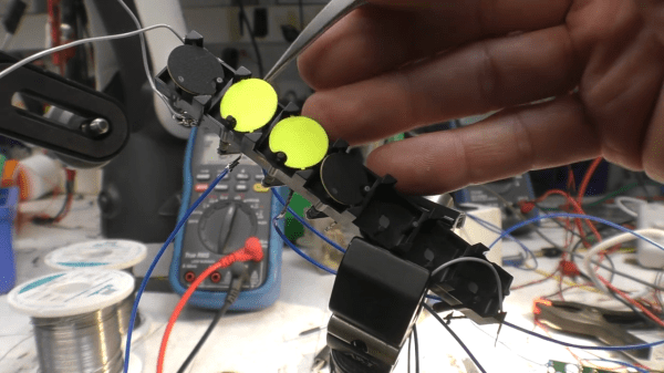
As he dismantled one of the flip-dots, he realized there was a lot going on under the hood than he realized. The dots are bistable — staying put when power is removed. This is achieved with a U-shaped electromagnet. The polarity of a driving pulse applied to the coil determines which way to flip the dot and saturates the electromagnet’s core in the process. Thus saturated, each dot is held in the desired position because the black side of the dot is made from magnetic material. But wait, there’s more — on further inspection, [Mike] discovered another permanent magnet mounted in the base. He’s not certain, but thinks its job is to speed up the flipping action.
 Besides curiosity, the reason [Mike] is studying these so closely is that he wants to build a different driver circuit to have better and faster control. He sets out to better understand the pulse waveform requirements by instrumenting a flip-dot and varying the pulse width and voltage. He determines you can get away with about 500 us pulses at 24 V, or 1 ms at 12 V, much better that the 10 ms he originally assumed. These waveforms result in about 60 to 70 ms flip times. We especially enjoyed the slow-motion video comparing the flip at different voltages at 16:55 in the video after the break.
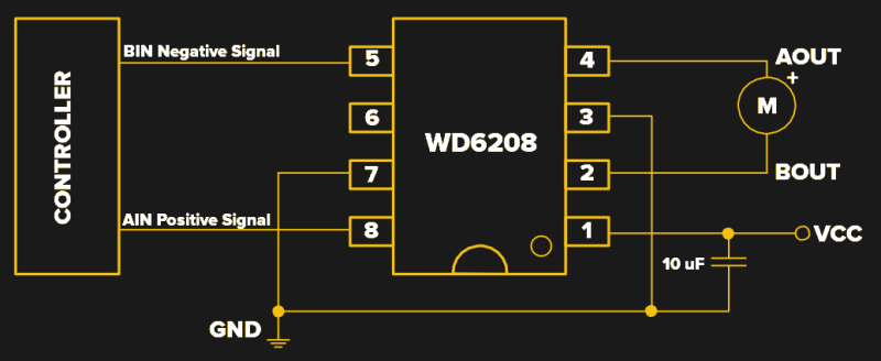
[Mike] still has to come up with the optimum driving circuit. He has tentatively has settled on a WD6208 driver chip from LCSC for $0.04/ea. Next he will determine the optimum technique to scale this up, deciding whether going for individual pixel control or a multiple sub-array blocks. There are mechanical issues, as well. He’s going to have to saw off the top and bottom margin of each panel. Reluctant to unsolder the 8500+ joints on each panel, his current idea is to solder new controller boards directly onto the back of the existing panels.
This video is a must-watch if you’re working on drivers for your flip-dot display project, and we eagerly look forward to any future updates from [Mike]. We also wrote about a project that repurposed similar panels a couple of years ago. There are a few details that [Mike] hasn’t figured out, so if you know more about how these flip-dots work, let us know in the comments below.
Continue reading “A Close Look At How Flip-Dot Displays Really Work”


