A Close Look At How Flip-Dot Displays Really Work

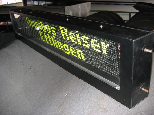
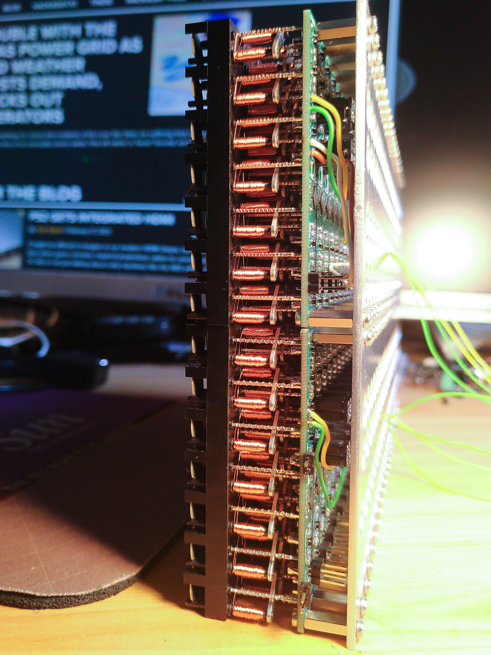
[Mike Harrison] has an upcoming project which will combine a large number of flip-dot displays salvaged from buses. [Mike] thought he knew how these things worked, and had a prototype PCB made right away. But while the PCB was being manufactured, he started digging deeper into the flip-dot’s flipping mechanism.

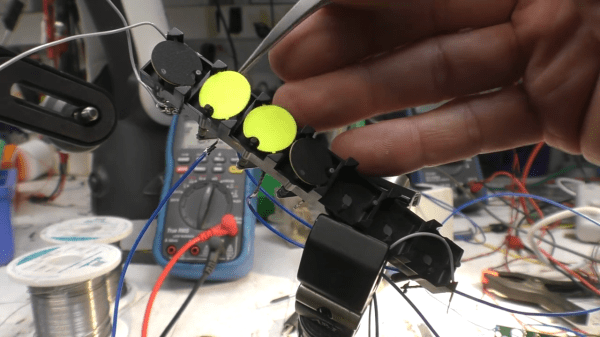
As he dismantled one of the flip-dots, he realized there was a lot going on under the hood than he realized. The dots are bistable — staying put when power is removed. This is achieved with a U-shaped electromagnet. The polarity of a driving pulse applied to the coil determines which way to flip the dot and saturates the electromagnet’s core in the process. Thus saturated, each dot is held in the desired position because the black side of the dot is made from magnetic material. But wait, there’s more — on further inspection, [Mike] discovered another permanent magnet mounted in the base. He’s not certain, but thinks its job is to speed up the flipping action.

Besides curiosity, the reason [Mike] is studying these so closely is that he wants to build a different driver circuit to have better and faster control. He sets out to better understand the pulse waveform requirements by instrumenting a flip-dot and varying the pulse width and voltage. He determines you can get away with about 500 us pulses at 24 V, or 1 ms at 12 V, much better that the 10 ms he originally assumed. These waveforms result in about 60 to 70 ms flip times. We especially enjoyed the slow-motion video comparing the flip at different voltages at 16:55 in the video after the break.

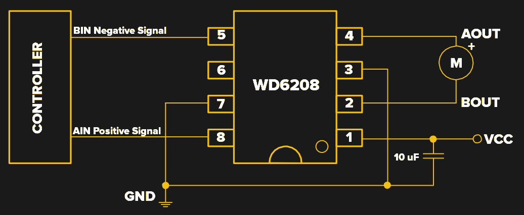
[Mike] still has to come up with the optimum driving circuit. He has tentatively has settled on a WD6208 driver chip from LCSC for $0.04/ea. Next he will determine the optimum technique to scale this up, deciding whether going for individual pixel control or a multiple sub-array blocks. There are mechanical issues, as well. He’s going to have to saw off the top and bottom margin of each panel. Reluctant to unsolder the 8500+ joints on each panel, his current idea is to solder new controller boards directly onto the back of the existing panels.

This video is a must-watch if you’re working on drivers for your flip-dot display project, and we eagerly look forward to any future updates from [Mike]. We also wrote about a project that repurposed similar panels a couple of years ago. There are a few details that [Mike] hasn’t figured out, so if you know more about how these flip-dots work, let us know in the comments below.

Continue reading “A Close Look At How Flip-Dot Displays Really Work”

30 FPS Flip-Dot Display Uses Cool Capacitor Trick

Most people find two problems when it comes to flip-dot displays: where to buy them and how to drive them. If you’re [Pierre Muth] you level up and add the challenge of driving them fast enough to rival non-mechanical displays like LCDs. It was a success, resulting in a novel and fast way of controlling flip-dot displays.

Gorgeous stackup of the completed display. [Pierre] says soldering the 2500 components kept him sane during lockdown.
If you’re lucky, you can get a used flip-dot panel decommissioned from an old bus destination panel, or perhaps the arrivals/departures board at a train station. But it is possible to buy brand new 1×7 pixel strips which is what [Pierre] has done. These come without any kind of driving hardware; just the magnetized dots with coils that can be energized to change the state.

The problem comes in needing to reverse the polarity of the coil to achieve both set and unset states. Here [Pierre] has a very interesting idea: instead of working out a way to change the connections of the coils between source and sink, he’s using a capacitor on one side that can be driven high or low to flip the dot.

Using this technique, charging the capacitor will give enough kick to flip the dot on the display. The same will happen when discharged (flipping the dot back), with the added benefit of not using additional power since the capacitor is already charged from setting the pixel. A circuit board was designed with CMOS to control each capacitor. A PCB is mounted to the back of a 7-pixel strip, creating modules that are formed into a larger display using SPI to cascade data from one to the next. The result, as you can see after the break, does a fantastic job of playing Bad Apple on the 24×14 matrix. If you have visions of one of these on your own desk, the design files and source code are available. Buying the pixels for a display this size is surprisingly affordable at about 100 €.

We’re a bit jealous of all the fun displays [Pierre] has been working on. He previously built a 384 neon bulb display that he was showing off last Autumn.

Continue reading “30 FPS Flip-Dot Display Uses Cool Capacitor Trick”

Flip Dot Displays Appear With Modernized Drivers

Admit it, you’ve always wanted to have your own flip-dot display to play with. Along with split-flap displays, flip-dots have an addictive look and sound that hearkens back half a century but still feels like modern technology. They use a magnetic coil to actuate each pixel — physical discs painted contrasting colors on either side. It means that you really only need electricity when changing the pixel, and that each pixel makes a satisfyingly unobtrusive click when flipped. The only problem with the displays is that they’re notoriously difficult to get your hands on.

flipdotBreakfast, a Brooklyn-based hardware firm known for creative marketing installations, unveiled their Flip-Disc Display System this morning. Used displays have come up on the usual sites from time to time, but often without a controller. Traditional flip-dot manufacturers haven’t sought out the individual hacker or hackerspace, and a click-to-buy option has been difficult if not impossible to find.

Breakfast’s offering modernizes the driver used to manage all of those electro-mechanical pixels. Whether this will make the displays more accessible is a question that still needs to be answered.
Continue reading “Flip Dot Displays Appear With Modernized Drivers”

Hacking A Flip Dot Display

While casually lurking on a famous auction website, [TeddyDesTodes] found the gem shown in the above picture and reverse engineered it. This is a flip dot display, the Brose Vollmatrix compact to be precise. It consists of a grid of small metal discs that are black on one side and yellow on the other, set into a black background. With power applied, the disc flips to show the other side. The disc is attached to an axle which also carries a small permanent magnet. Positioned close to the magnet is a solenoid. By pulsing the solenoid coil with the appropriate electrical polarity, the magnet will align itself with the magnetic field, also turning the disc.

After carrying the 25kg display from his post office to home, [TeddyDesTodes] opened it and discovered that the main control board was using two RS422 transceivers. So he fired up his bus pirate, started to sniff the traffic and noticed that several commands were repeatedly sent. [TeddyDesTodes] stopped the transmission, sent these particular commands and had the good surprise to see some dots flipped. From there, displaying something was a piece of cake.

If this is familiar to you it may be because it was shared in one of the Trinket Contest Updates. But the background details were just so much fun we think this deserves a full feature of it’s own. Do you agree?