
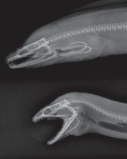
The four bar linkage is a type of mechanical linkage that is used in many different devices. A few examples are: locking pliers, bicycles, oil well pumps, loaders, internal combustion engines, compressors, and pantographs. In biology we can also find examples of this linkage, as in the human knee joint, where the mechanism allows rotation and keeps the two legs bones attached to each other. It is also present in some fish jaws that evolved to take advantage of the force multiplication that the four bar mechanism can provide.
How It Works
Mechanical linkages in general are a group of bodies connected to each other to manage forces and movement. The bodies, or links, that form the linkage, are connected to each other at points called joints. Perhaps the simplest example is the lever, that consists of a rigid bar that is allowed to pivot about a fulcrum, used to obtain a mechanical advantage: you can raise an object using less force than the weight of the object.
Two levers can be connected to each other to form the four bar linkage. In the figure, the levers are represented by the links a (A-D) and b (B-C). The points A and B are the fulcrum points. A third link f (C-D) connects the levers, and the fourth link is the ground or frame g (A-B) where the mechanism is mounted. In the animation below, the input link a (the crank) performs a rotational motion driving the rocker rod b and resulting in a reciprocating motion of the link b (the rocker).


This slider-crank arrangement is the heart of the internal combustion engine, where the expansion of gases against a sliding piston in the cylinder drives the rotation of the crank. In a compressor the opposite happens, the rotation of the crank pushes the piston to compress the gas in the cylinder. Depending on how the mechanism is arranged, it can perform the following tasks:
- convert rotational motion to reciprocating motion, as we just discussed above.
- convert reciprocating motion to rotational motion, as in the bicycle.
- constrain motion, e.g. knee joint and car suspension.
- magnify force, as in the parrotfish jaw.
Some Applications
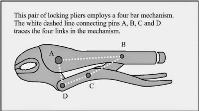
One interesting application of the four bar linkage is found in locking pliers. The B-C and C-D links are set at an angle close to 180 degrees. When force is applied to the handle, the angle between the links is less than 180 (measured from inside the linkage), and the resulting force in the jaws tries to keep the handle open. When the pliers snap into the locked position that angle becomes less than 180, and the force in the jaws keeps the handle in the locked position.
 In a bicycle, the reciprocating motion of the rider´s legs is converted to rotational motion via a four bar mechanism that is formed by the two leg segments, the bicycle frame, and the crank.
The joints connecting the links in the linkage can be of two types. A hinged joint is called a revolute, and a sliding joint is called a prismatic. Depending on the number of revolute and prismatic joints, the four bar linkage can be of three types:
- Planar quadrilateral linkage formed by four links and four revolute points. This is shown in the animation above.
- Slider-crank linkage, formed by three revolute joints and a prismatic joint.
- Double slider formed by two revolute joints and two prismatic joints. The Scotch yoke and the trammel of Archimedes are examples.
There are a great number of variations for the four bar linkage, and as you can guess, the design process to obtain the forces and movements that we need is not an easy task. An excellent resource for the interested reader is KMODDL (Kinematic Models for Design Digital Library) from Cornell University. Other interesting sites are the 507 mechanical movements, where you can find nice animations, and [thang010146]’s YouTube channel.
We hope to have piqued your curiosity in mechanical things. In these times of ultra fast developments in electronics, looking at the working of mechanisms that were developed centuries ago, but are still present and needed in our everyday lives can be a rewarding experience. We plan to work on more articles featuring interesting mechanisms so please let us know your favorites in the comments below.


Fun interactive linkage designer, previously seen here on HaD: http://blog.rectorsquid.com/linkage-mechanism-designer-and-simulator/
Beat me to the link in just a few seconds! :)
Great minds think alike. And have a better memory of HaD content than the editors.
Several commenters seems to believe that HaD editors are core static group that never changes. This is not the case. It’s extremely fluid. And some of the new authors may have only read HaD for the past couple of years so have no clue what’s been posted in the past.
Should they Google? Yeah, probably.
Well, it should be the editors duty to double check if a certain link/item had been posted before…
Yet, having been sending tips to HaD for the past several years, learned the hard way to check if my links were posted before. Once sent a link and caused a second posting of this:
http://hackaday.com/2012/10/18/most-useless-machine-building-elevator-edition/
Don’t they have some kind of database?
>”Don’t they have some kind of database?”
Each article seems to come with searchable tags, so yes.
But what’s the use of it, if you can’t remember the keywords?
That is incredible. I don’t remember seeing that one go by back in December. Thanks!
Waa, boo hoo. Someone has seen an article before. Get over yourself. Some people haven’t. There isn’t an Eleventh Commandment that says “Verily, Everything Must Be New”. Yes, Hackaday should report new stuff but they should also bring old stuff to the attention of new people.
If you want to check out linkages yourself (of any type, not just four bar) in a nice simple simulator, here’s one:
http://blog.rectorsquid.com/linkage-mechanism-designer-and-simulator/
Tried it myself, very intuitive and easy to learn.
Thanks, enjoyed the rolling ball sculpture.
I have the printed version of the “507 Mechanical Movements” – had no idea there was now an animated website.
I’ve got one of those… also check archive.org for a few more.
There’s one of them, see similar items at bottom. …..
https://archive.org/details/mechanicalappli00dextgoog
By the way, isn’t a sporting cyclist using a 5 bar linkage, with a toe clip and pivot at heel and under toe???
Maybe, but I want to say from my limited cycling experience that proper form is to avoid moving your ankle if possible, turning the lower leg and foot into a single rigid link.
Even if it does allow movement it would be small relative to the rest of the system. It could probably still be modeled as a 4 bar within a reasonably small error.
Of course I’ve not actually modeled this particular scenario. I could be very, very wrong.
Yah I can see that on the downstroke, but I thought the ankle moved free on the upstroke.
Oh heck, yeah, the ankle is involved. Though I am just a cycle commuter (i.e. would never ride a bike for fun) I spent many, many hours watching my three kids train and go on to compete nationally and one who went on to the Pan-Ams. And, yep, that ankle moves a lot. According to a technique guide here: http://www.bicycling.com/training/fitness/perfect-pedal-stroke the ankle joint goes through 30 degrees in a cycle.
Wow that’s actually quite a bit different than I thought, more akin to my recreational stroke, with the heel low on the down. Thought they went full point into the toe straps.
Seems like bunk science to me. It’s just extra muscle action, as moving the ankle works against the upper leg.
The benefit is listed as ” up to 5 bpm lower heart rate” which is something so hard to measure in real life that it also makes it smell like a red herring.
What’s the explaination of why it should work?
I thought the idea is to use more muscles together, so you can apply extra power or speed to the motion. Probably only of interest for racers.
Riddle me this: if you have two hydraulic cylinders, each with a maximum force of 30 kN, and you connect them end to end, what is your maximum force? Answer: 30 kN, because one cylinder is pushing against the other and you shall not exceed the load capacity of either.
Same thing with the leg muscles. If you push down with your toes, you’re also pushing up against the thigh muscles, and the thigh muscles must work to push down or else your knee would go up instead of down and the pedals wouldn’t turn. You’d just sit there bobbing your knees up and down instead of pedaling the bike.
If you want to generate a downward force on the peda, both sets of muscles must bear the same force or else the force system is not balanced and the system is not rigid …which means you now have two sets of muscles working for the same effect as one set, which by all logic would be spending more energy without gaining any power at the crank. One set is working just to keep your lower leg stiff against the pedal, which is completely unnecessary.
Recreational cyclist (including mountain unicycling) here. I’ve read a couple books on cycling from a physics POV and I think the advantage of ankle movement comes from the flex around the top of the stroke, reducing the distance the relatively-heavy leg must be lifted over (or pushed over by the other leg).
With crank-integrated watt meters, heart-rate monitor/recorders, and thousands of hours of knowing one’s bodily responces, 5bpm is way above the noise floor, even for experienced recreational riders. When I’m on a hard climb, I sometimes find myself maxing out on bpm and falling into inefficient technique and once I get back in the groove with proper technique, I can find 5bpm easily.
Enjoyed this!
There are so many fascinating mechanisms out there, thanks for the links!
If you like linkages, complex calender mechanisms in many clocks and watches use a lot of simple linkages for really cool results. Get a copy of Modern Calender Watches by B. Humbert- it’s nothing but linkage and gears and racks- geometric engineers porn.
The Four-Bar Linkage – an old friend…
When you go to University for your Engineering Degree, once you finish your fundamental Physics and Calculus/Differential-Equations courses you should be required to take two basic courses in Mechanical Engineering. (No matter what your target engineering discipline is at graduation, you MUST get this knowledge from your school – otherwise enroll elsewhere):
(1) Engineering Statics, and (2) Engineering Dynamics
Here are some pertinent terms (working from memory here):
* Statics: The study of forces on a rigid body not in-motion.
* Dynamics: The study of forces on a rigid body in-motion.
* Kinematics: A subset of Dynamics without the forces causing motion.
* Kinetics: A subset of Dynamics only about the forces causing motion.
After you complete the Statics and Dynamics courses, you should also be required to study a third discipline involving non-rigid bodies. This is often called Fluids or Fluid Dynamics. A basic Engineering degree should also require a course in Mechanics of Materials. These are disciplines being omitted from “Quick” so-called “EECS” degrees that are absolutely necessary (IMO) if you are to survive long-term as a practicing Professional. Disclosure – I’m an older EE spawned from what I consider a good university that at the time still adhered to making Real Engineers – not Technicians.
good
A good mechanism design and simulation tool I recently came across on JBVCreative’s YouTube channel is MotionGen . http://www.motiongen.io