A handheld device to measure electromagnetic fields

Measuring Electromagnetic Fields With Just An Arduino And A Piece Of Wire

Electromagnetic interference problems can be a real headache to debug. If you need to prove what causes your WiFi to slow down or your digital TV signal to drop, then the ability to measure electromagnetic fields (EMF) can be a big help. Professional equipment is often very expensive, but building an EMF detector yourself is not even that difficult: just take a look at Arduino expert [Mirko Pavleski]’s convenient hand-held electromagnetic field detector.

The basic idea is quite simple: connect an antenna directly to an Arduino’s analog input and visualize the signal that it measures. Because the input of an ADC is high impedance, it is very sensitive to any stray currents that are picked up by the antenna. So sensitive in fact, that a resistor of a few mega-Ohms to ground is required to keep the sensor from triggering on any random kind of noise. [Mirko] made that resistance adjustable with a few knobs and switches so that the detector can be used in both quiet and noisy environments.

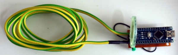
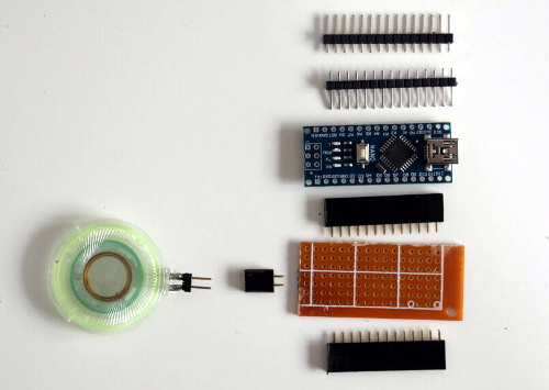
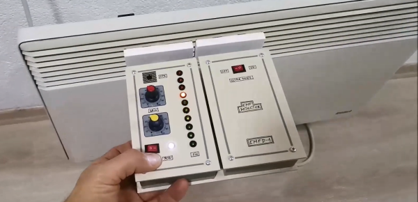
Making the whole device work reliably was an interesting exercise in electromagnetic engineering: in the first few iterations, the detector would trigger off its own LEDs and buzzer, trapping itself in a never-ending loop. [Mirko] solved this by encasing the Arduino inside a closed, grounded metal box with only the required wires sticking out. The antenna’s design was largely based on trial-and-error; the current setup with a 7 cm x 3 cm piece of aluminium sheet seemed to work well.

While this is not a calibrated professional-grade instrument, it should come in handy to find sources of interference, or even simply to locate hidden power cables. You can view this as a more advanced version of [Mirko]’s Junk Box EMF Detector; if you have a second Arduino lying around, you can use that one to generate interference instead. Continue reading “Measuring Electromagnetic Fields With Just An Arduino And A Piece Of Wire”

Simple Probe Sniffs Out EMI

Unable to account for the strange glitches he was seeing on his DIY CNC router, [Daniël Van Den Berg]  wondered if his electronics might be suffering from some form of electromagnetic interference (EMI). So he did what any good hacker would do, and rummaged through the parts bin to build an impromptu EMI detector.

[Daniël] is quick to point out that he’s not an electrical engineer, and makes no guarantees about the accuracy of his tossed together gadget. But it does seem to work well enough in his testing that he’s able to identify particularly “noisy” electronic components, so it’s probably worth putting one together just to hear what your hardware is pumping into the environment.

The hardware here is very simple, [Daniël] just attached a coil of solid copper wire to one of the analog pins on an Arduino Nano with a resistor, and hung a speaker off of one of the digital pins. From there, it just took a few lines of code to read the voltage in the coil and convert that into a tone for the speaker. The basic idea is that a strong alternating magnetic field will set up voltage fluctuations in the coil large enough for the Arduino’s ADC to read.

If you’re looking for a bit more insight into what kind of interference your electronic creations might be putting out, [Alex Whittimore] gave a fantastic presentation during the 2020 Hackaday Remoticon about performing RF debugging using a cheap RTL-SDR dongle.

Camera Sees Electromagnetic Interference Using An SDR And Machine Vision

It’s one thing to know that your device is leaking electromagnetic interference (EMI), but if you really want to solve the problem, it might be helpful to know where the emissions are coming from. This heat-mapping EMI probe will answer that question, with style. It uses a webcam to record an EMI probe and the overlay a heat map of the interference on the image itself.

Regular readers will note that the hardware end of [Charles Grassin]’s EMI mapper bears a strong resemblance to the EMC probe made from semi-rigid coax we featured recently. Built as a cheap DIY substitute for an expensive off-the-shelf probe set for electromagnetic testing, the probe was super simple: just a semi-rigid coax jumper with one SMA plug lopped off and the raw end looped back and soldered. Connected to an SDR dongle, the probe proved useful for tracking down noisy circuits.

[Charles]’ project takes that a step further by adding a camera that looks down upon the device under test. OpenCV is used to track the probe, which is moved over the DUT manually with the help of an augmented reality display that helps track coverage, with a Python script recording its position and the RF power measurements. The video below shows the capture process and what the data looks like when reassembled as an overlay on top of the device.

Even if EMC testing isn’t your thing, this one seems like a lot of fun for the curious. [Charles] has kindly made the sources available on GitHub, so this is a great project to just knock out quickly and start mapping.

Continue reading “Camera Sees Electromagnetic Interference Using An SDR And Machine Vision”

Build Your Own EMI Probes

[Gerald Musy] wanted to investigate the source of electromagnetic interference (EMI) in his switching power supply design. Stymied by the high cost of EMI probes, he decided to build his own. Lucky for us, he wrote up his results of experimenting with four different designs.

The probes include an unshielded loop, a shielded loop, a ferrite core probe, and an electric field probe. None of these are especially complex to build–the ferrite core one is probably the most involved–you can see from the scope traces that the different probes pick up different information.

Continue reading “Build Your Own EMI Probes”