Jet Engine Tachometer Turned Into Unique CPU Utilization Meter

When you’ve got a piece of interesting old aviation hardware on your desk, what do you do with it? If you’re not willing to relegate it to paperweight status, your only real choice is to tear it down to see what makes it tick. And if you’re lucky, you’ll be able to put it to work based on what you learned.

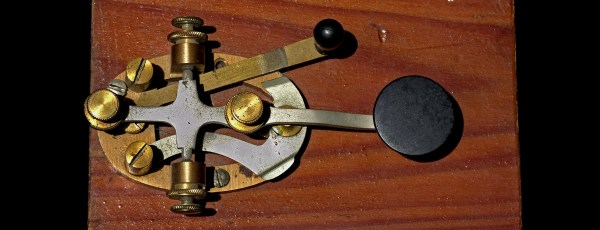
That’s what happened when [Glen Akins] came across a tachometer for a jet airplane, which he promptly turned into a unique CPU utilization gauge for his computer. Much of the write-up is concerned with probing the instrument’s innards to learn its secrets, although it was clear from the outset that his tachometer, from Kollsman Instruments, was electrically driven. [Glen]’s investigation revealed a 3-phase synchronous motor inside the tach. The motor drives a permanent magnet, which spins inside a copper cup attached to the needle on the tach’s face. Eddy currents induced in the cup by the spinning magnet create a torque that turns the needle against the force of a hairspring. Pretty simple — but how to put the instrument to work?

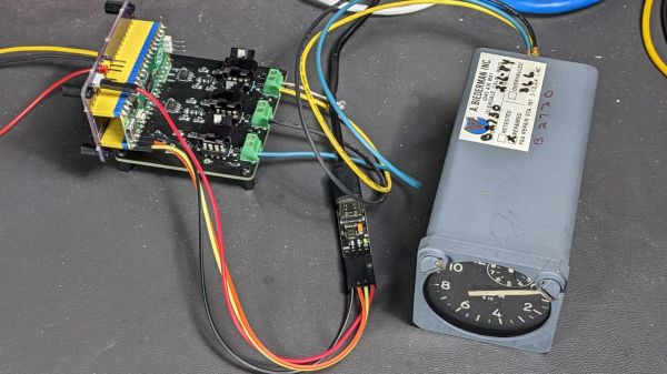
[Glen]’s solution was to build what amounts to a variable frequency drive (VFD). His power supply is based on techniques he used to explore aircraft synchros, which we covered a while back. The drive uses a trio of MCP4802 8-bit DACs to generate three phase-shifted sine waves via direct digital synthesis with an RP2040. The 3-phase signal drives the motor and spins the dial, with 84-Hz corresponding to full-scale deflection.

The video below shows the resulting CPU utilization gauge — which just queries for the current load level and sends it to the RP2040 over serial — in action. It’s not exactly responsive to rapid changes, but that’s to be expected from a mechanical system. And compared to exploring such a nice instrument, it really doesn’t matter.

Continue reading “Jet Engine Tachometer Turned Into Unique CPU Utilization Meter”

Serially, Are You Syncing Or Asyncing?

I know you’ve heard of both synchronous and asynchronous communications. But do you really know the differences between the two?

Serial communication was used long before computers existed. A predecessor is the telegraph system using Morse Code, one of the first digital modes of communication. Another predecessor is the teletype, which set standards that are still used today in your Arduino or Raspberry Pi.

All you need is two wires for serial communications, which makes it simple and relatively robust. One wire is ground and the other the signal. By interrupting the power with predefined patterns, information can be transferred over both short and long distances. The challenge is receiving the patterns correctly and quickly enough to be useful.

I was a bit surprised to find out the serial port on the Arduino Uno’s ATmega328P microcontroller is a Universal Synchronous Asynchronous Transmitter Receiver (USART). I’d assumed it was only a UART (same name, just leave out synchronous) probably because my first work with serial communications was with the venerable Intel 8251 “Programmable Communication Interface”, a UART, and I didn’t expect the microcontroller to be more advanced. Silly me. Later I worked with the Zilog 8530 Serial Controller Chip, a USART, the term I’ll use for both device types.

All these devices function in the same way. You send a byte by loading it into a register and it is shifted out one bit at a time on the transmit (TX) line as pulses. The receiver accepts the pulses on a receive (RX) input and shifts them into a register, which is then read by the system. The transmitter’s job is pretty easy it just shifts out the bits at a known clock rate. The receiver’s task is more complex because it needs to know when to sample the incoming signal. How it does this is the difference between asynchronous and synchronous communications.

Continue reading “Serially, Are You Syncing Or Asyncing?”