Rebuilding The Electronics In A Remote Control Car

Inspired by the many autonomous rovers such as Curiosity and the self-driving Google car, [Rohit] decided to build his own by taking an off-the-shelf remote control car and adding his own electronics. Unfortunately, he couldn’t find the datasheet for the chip used to receive radio signals and drive the motors, so he ended up building his own electronics and putting them in the car.

[Rohit]’s car – the Thunder Rumbler RC Car – is driven by applying power to two motors. This is an easy system to control, as only two channels are needed to make the car go forward, left, right, or backwards. To drive these two motors, [Rohit] found an SN754410 quadruple half-H bridge driver chip lying in his box of assorted electronic components. Thanks to a helpful instructable, this chip was easily controlled with an Arduino.

That left the problem of sending a wireless signal to the Arduino. [Rohit] accomplished this by relying on an Android phone to provide the remote control.

[Rohit] whipped up a small program running on his desktop that allows him to send ‘L’, ‘R’, ‘U’, or ‘D’ to the Android phone to dictate if the car should go left, right, forward, or reverse. The Android phone receives these commands via the Internet and sends an audio signal through the headphone port. This audio signal is connected to two analog pins of the Arduino. With a little bit of software and a bit of reading up on frequency shift keying, [Rohit] was able to make his car move in any direction.

Even though [Rohit] realized his goal of controlling a remote control car on his own terms, the build is far from done. He plans on adding some ultrasonic sensors and using the Android’s camera for object detection.

Building A Driver For Absurdly High Power LEDs

A few years ago, the highest power LEDs you could buy capped out around three watts. Now, LED manufacturers are taking things to ridiculous power ratings with 30, 40, and even 90 watt LEDs. Getting these high-power LEDs are no longer a problem, but powering them certainly is. [Thomas] built a LED driver capable of powering these gigantic LEDs and creating a light show that is probably bright enough to cause bit of eye damage.

[Thomas]’ LED driver is based on Linear Technology’s LT3518 LED driver. This driver is part of a project to build a huge WiFi controlled RGB LED, so the driver has outputs for three separate LEDs capable of sourcing 700 mA each.

Because [Thomas] is dealing with crazy amounts of heat and power required to light up these huge LEDs, the driver board features a temperature sensor next to each LED driver. When the board gets too hot, the driver automatically shuts down, preventing bad things from happening.

You can check out a few pictures of [Thomas]’ LED driver over on the build page for his WiFi LED project. A truly awesome amount of lighting power here, that also makes it impossible to get a good picture of the board in operation.

Etching Your Own PCBs At Home

Etching your own PCBs from copper clad board is nothing new, but the ability to make your own circuit boards at home is so useful it should be part of every maker’s repertoire of skills. The folks over at Hub City Labs in Moncton, NB, Canada put together a workshop covering the basics of home PCB manufacturing, allowing any maker to put a circuit board in their hands in under an hour.

The process starts just like any PCB design – laying out traces, parts, and vias in a PCB designer such as Eagle. When making your own boards, it’s a good idea to make the traces and pads extra large; the folks at Hub City Labs follow the 50-50 rule: 50 mil wide traces with 50 mils of seperation.

The PCB design is printed out with a laser printer (in mirror mode) onto a piece of paper from a glossy magazine or inkjet photo paper. After the copper board is scrubbed to remove any oxidation or oils present, the design is laid face down on the copper and heated with a clothes iron or sent through a laminator.

After the laser printer toner is transferred to the copper, the recipe calls for etching the board with a solution consisting of a half cup of 3% Hydrogen Peroxide and a quarter cup of muriatic acid.

The folks at Hub City Labs put together a great tutorial for one of the most useful skills the home electronics wizard can have, but etching your own PCBs is an art unto itself. There’s a lot of ways this process can be improved, from using Kapton tape to secure the printed art to the copper board, to getting high-strength peroxide from a beauty supply store.

If you’ve got any tips on making your own PCBs at home, drop a line in the comments below.

EDIT: Good job killing Hub City Lab’s web server, everybody. They’re working on getting something up.

Party Photo Printer Built Around A Raspberry Pi

We think [Brian Delacruz] latched on to a good idea with this photo printer project. Instead of building a big photo booth for his party he developed a Raspberry Pi based WiFi photo printer. Right now it’s a prototype that lacks the kind of polish necessary to make a true user-friendly device. But the idea is solid and just waiting for you to improve upon it.

In addition to the RPi he’s using a quality photo printer and a small wireless router. The router simply provides WiFi capabilities for the RPi which is running a web server, mySQL, and FTP. This provides a wide range of upload options which he can work with. Watch the video after the break to see him print a smart phone photo wirelessly.

This can be simplified by using a package like hostapd to use a USB WiFi dongle as an access point. Or if the venue already has Internet access a server could be set up with a QR code to guide people to it. The party starts off with an empty bulletin board and guests would be invited to print and hang their own photos which will go into the host’s guest book/scrap book to remember the event.

Data From Your Coffee Maker Turned Into Art

This is what your coffee looks like as it is being brewed. The three different art pieces seen above were generated based on data from different parts of a high-end coffee maker. This isn’t a bargain basement single switch drip maker (we reserve those for NES retrofits) but a top-of-the-line espresso machine. And before you cry foul we’ll warn you that the project is a marketing device for the manufacturer. But we still think it’s interesting so read on or jump directly to the video after the break.

We’re unsure if the sensors are normally included in the machine or if they were added during the hack. An Arduino pulls in data about the brew process from two flow meters, a steam indicator LED, and three thermistors. The measured values are sent to a Processing application which turns them into the generative art seen above. What results is a widescreen display that aims to turn your bleary-eyed wait for morning coffee into something interesting.

Continue reading “Data From Your Coffee Maker Turned Into Art”

ARM-based Debugging Tool Aims To Improve On The Bus Pirate Performance

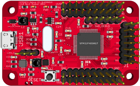
The Bus Pirate is a fantastic development tool. It does an amazing job at a lot of different things. And as it has matured, community support has driven it to new areas beyond the original design. This is where its hardware holds back performance a little bit. For instance, as an I2C or SPI sniffer it has limited capture speed. That’s the type of thing that this board could improve upon. It’s a debugging tool based on an STM32 F4 microcontroller. That’s an ARM Cortex-M4 chip which runs at 168 MHz, and has 192 KB of SRAM.

[TitanMKD] has been working on the design but it is still just in digital form. Since there’s no prototype there is also no firmware for the device. That’s a tall mountain to climb and it’s one of the reasons we’re featuring the project now. [Titan’s] plan is to model this after the Bus Pirate interface. We think it’s a good idea since a lot of folks have already learned the syntax. We didn’t see a contact form on his site, but if you’re interested in contributing to the project you might want to leave a comment here or on his project page (linked above).

Gilded Hello Kitty Ax Made Using Electrolysis

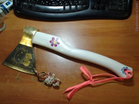
Ummm…. cute? For the Hello Kitty fan who has everything?

Yeah, we’re really not sure what’s going on here. It’s an art piece on which [Denis] spent a lot of time. He polished it, etched it, painted it, applied gold leaf, and drilled a hole for a charm. It’s that hole which interested us the most. He had a heck of a time figuring out how to make a hole in the hardened steel. The solution that finally worked was to use electrolysis to bore through the metal (translated).

[Denis] first made a small depression where he wanted the hole. This took time, and pretty much ate through the engraver bit he was using. But it was just enough to hold a drop of saline. He connected the positive side of his power supply to the ax head, then dipped the negative lead into the drop of saline. Each time the drop turned black he wiped it away and replaced it with fresh solution. Just five hours of this and a pack or two of cotton swabs and he was through.