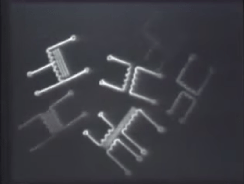
Whether you’re just getting into electronics or could use a refresher on some component or phenomenon, it’s hard to beat the training films made by the U.S. military. This 1965 overview of transformers and their operations is another great example of clear and concise instruction, this time by the Air Force.
It opens to a sweeping orchestral piece reminiscent of the I Love Lucy theme. A lone instructor introduces the idea of transformers, their principles, and their applications in what seems to be a single take. We learn that transformers can increase or reduce voltage, stepping it up or down through electromagnetic induction. He moves on to describe transformer action, whereby voltages are increased or decreased depending on the ratio of turns in the primary winding to that of the secondary winding.
He explains that transformer action does not change the energy involved. Whether the turns ratio is 1:2 or 1:10, power remains the same from the primary to the secondary winding. After touching briefly on the coefficient of coupling, he discusses four types of transformers: power, audio, RF, and autotransformers.
Power transformers are designed to operate at a specific frequency to step AC voltage up or down. They usually have iron cores and one or more secondary windings. Audio transformers operate over the spectrum of audible frequencies, between ~20 to ~20,000 cycles per second, as they are called here. Radio Frequency or RF transformers are used at frequencies north of 20KHz, and are prone to hysteresis and eddy currents. Therefore, they usually have air cores.
Autotransformers use a single winding for both coils. In a step-up transformer, the turns of primary winding constitute a percentage of the windings in the secondary, and vice versa for step-down units. Some autotransformers are of variable action. These operate similarly to potentiometers, and are commonly referred to as variacs.
In conclusion, the instructor applies this knowledge by using voltage and resistance measurements to identify unknown turns ratios. Finally, he checks for open and short windings on a PSM-6 mulitmeter.
[via reddit]
http://www.youtube.com/watch?v=a4pxpG83LUY
Retrotechtacular is a weekly column featuring hacks, technology, and kitsch from ages of yore. Help keep it fresh by sending in your ideas for future installments.


These videos are ALWAYS AWESOME! I love the way they explain things!
They made a grave omission though.
Measuring the resistance of the windings to infer the turns ratio assumes that both windings are made with the same type and gauge of wire, and of the same material. It’s often the case that one of the windings is made with thinner wire to fit more in.
Same thing with the detection of a shorted winding; one doesn’t know what the resistance of a 300 turn winding should be from measuring another 300 turn winding unless they’re both from the exact same make and model of a transformer.
At 6:35, those input fields look like perfectly normal html fields
wtf are you talking about?
No idea what he’s on about, but the stretchy letters sliding up and down were interesting.
Probably meant @6:53, not 6:35…
Alternate article title for the younger generations: “Transformers – More Than Meets The Eye!”
i knew i’d see this here the moment i saw it on reddit
Reminds me of my sixth form physics teacher Mr Courtney. Except this guys doesn’t shout or randomly cane people if they aren’t paying attention.
Wro-ong! Do it again!
at around 2:45 he mentions that if you grab the wire with your left hand with the thumb in the direction of the current, the magnetic field lines will circle the wire in the direction of your fingers. This is the opposite of what I was taught as the “right hand thumb rule”. Is he referring to the flow of electrons as opposed to “conventional current”? Is there something I’m missing here?
If you grab the output wire of a 10,000 V transformer in either hand, the direction of the field is the least of your worries.
Left Hand Rule #1
This rule is used to determine either the magnetic field or the current traveling around a rod of some sort. This is the only case in which this rule applies.
Pretend you are wrapping your fingers around an imaginary rod curing the fingers in the direction of the Magnetic field (B-field). The thumb will then point in the direction of the current (I).