Here’s a tip from a wizened engineer I’ve heard several times. If you’re poking around a circuit that has failed, look at the resistor color codes. Sometimes, if a resistor overheats, the color code bands will change color – orange to brown, blue to black, and so forth. If you know your preferred numbers for resistors, you might find a resistor with a value that isn’t made. This is where the circuit was overheating, and you’re probably very close to discovering the problem.
The problem with this technique is that you have to look at and decode all the resistors. If automation and computer vision is more your thing, [Parth] made an Android app that will automatically tell you the value of a resistor by pointing a camera at it.
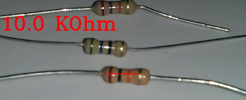
The code uses OpenCV to scan a small line of pixels in the middle of the screen. Colors are extracted from this, and the value of the resistor is displayed on the screen. It’s perfect for scanning through a few hundred through hole resistors, if you don’t want to learn the politically correct mnemonic they’re teaching these days.
Video below, and the app is available for free on the Google Play store.


What, we have to learn about electronics without racist rape jokes now? What’s next!? Get off my lawn.
It’s not racist-at least not the one I learned.
The version I first learned was ‘bad boys…’. I didn’t learn the racist version until much later.
Offensive as it is I bet you remembered it after the first time you heard it!
Violet’s not a slut…she’s just drawn that way.
Wow, I had never heard that mnemonic device.. google saved the day, won’t be forgetting that one!
looks cool, thanks
No red line to scan. Just a white box around the edges of my phone. Oh how I wished this worked!
Don’t bother with that app, it is unusable. I have tried it out of curiosity, because I deal with computer vision quite a bit. Reading resistors using a camera is challenging, because the strip colours are not really standard – red strip on one could look like a brown on another one. Also a lot depends on the lighting, whether the resistor is dirty, etc.
Unfortunately, the app doesn’t deal with any of this – it is a naive implementation that will read the codes in the ideal conditions if the colours match whatever it has hardwired. What is worse, the usability is horrible – it will read the resistor only when you have it aligned with the short red line in the middle. On my HTC One it will use the highest zoom setting for whatever reason (not adjustable!), so you have to hold the phone 40-50cm away from the resistor at high zoom, with the image shaking like crazy. And then it decodes a 68k resistor as anything between 1R to 800R … Epic fail.
A lot more practical solution is a multimeter or, if you have a lot of resistors to test quickly, one of those universal testers like this one:
http://i.ebayimg.com/00/s/NTM2WDcxMQ==/z/kTIAAOxyYANTYKoo/$_57.JPG
I’ve actually tried writing a similar app before, but I stopped after the initial proof of concept for id’ing colors. It’s amazingly difficult to examine a group of pixels and determine “red” correctly. I mostly tried to define colors as ratios ranges of the RGB values, which you think would work. Then I realized I hardly ever use through hole resistors anymore and gave up on ot.
We old hacker/makers have boxes of resistors galore, for breadboarding and even fly-wiring. At 70, its getting more difficult to read the codes and any help is greatly appreciated. I hope that you, or someone, will continue to improve the app.
Just use an ohmmeter or get the little tester I have linked to before from eBay. They cost less than $20 delivered. You will be way better served than having to fiddle with the phone (and requiring to have a fragile phone on the bench in the first place). Also, there are a lot of resistors that don’t have colour code (numeric marking, wiped off, etc.), so you will have to measure them anyway.
I don’t think you understood Andy.
The zoom factor alone would be important for someone who has age diminishing sight. Sure I could use a meter and test the resistor, and test an insect dropping, test a speck of dust. I could even test a lighting reflection.
This project has potential and could go a lot further, perhaps even identifying SMD parts Via OCR.
As an older person I already use a camera instead of my eyes.
An ohmmeter doesn’t help for in-circuit resistors unfortunately.
I am colour blind and have a visual impairment and resistors are becoming almost impossible to deal with. I certainly could use a camera-based solution.
i’ve been looking into those on ebay after reading up on ESR (EQUIVALENT sERIES rESISTANCE METERS) WHICH CAN CAN READ VALUES WHILST STILL IN CCT. IS THIS THE SAME, as its a lot cheaper but gives the impression u have to take components out of cct… proper ESR meters r twice as dear as these..
@Rob Rob, the zoom is useless if you can’t hold the resistor in the scanning zone because of the extreme camera shake (zoom magnifies the shake too). You would have to have it mounted on a tripod. Not very practical.
@Luke You could use an ESR meter for in-circuit testing of small value resistors, but it is more reliable to lift one leg of the resistor anyway. Camera testers are going to be always unreliable, unless you are using resistors from one manufacturer/series, with fixed lighting and fixed camera (i.e. in some sort of automated machine). Tester that you cannot trust to give you a correct value is worse than no tester at all, IMO.
@Jan, you are just not getting that this is completely subjective. For example – you said: “the zoom is useless if you can’t hold the resistor in the scanning zone because of the extreme camera shake (zoom magnifies the shake too). You would have to have it mounted on a tripod. Not very practical”!
Well get this … I use a 30x Zoom DSLR camera on a tripod extremely frequently. In fact there is not much in the SMD world that I can identify without this setup. I have a second camera that I use as a hand held. It has very good image stabilisation at high zoom. What I don’t use … is my naked eyes.
Now, I fully get that you think this setup is useless because you can just look at the smaller parts and identify them just with eye sight. I can’t and not long after 40 years of age you wont be able to either.
So what you call “Not very practical” is absolutely essential for others.
With an aging population there will be a greater and greater percentage of older people on the work force.
This project has absolutely huge potential especially if it can use OCR tech to work with SMD.
Same here, I only use through hole resistors when I need high wattage or rare/ extra high/ extra low values.
I remembered the colour series probably when I was in the young teens and the values stuck in my head since. For the 5% resistor, there are only 24 patterns (E24) for identifying values on the first two rings and may be 5-6 for multiplier ring. After working with resistors for a while, you should be see the common values as pattern and not having to work out the values. I kept most of my through hole resistors in a big bag and find them by pattern and have been doing that for decades. It is a good exercise for the brains.
and then along came switched mode supplies, wtf fractional resistors :eek:
RGB is not a perceptually uniform color space you should convert it to something like CIE-LAB first, then you can measure Euclidean distances or Delta-E.
I just got the yellow tester reviewed on here recently, really cheap and clear. That said I used to use a lot of things I now just use my phone for. I suppose it could be improved with a small calibration card for wb, 50% gray, black, gamma etc.
That won’t help you any, unfortunately. Get a bunch of resistor from another manufacturer/batch and the colors will be off again. Get a slightly different lighting and the calibration is off, etc.
The E24 and E12 systems precisely specify not only the band colors but also the base color of the resistors. You may not be aware of this but the standard colors also fall into a grey scale so that color blind people can read them as well.
For a very long time it didn’t matter at all ‘where’ you bought resistors. It is only in more recent times that we have cheap resistors flowing in from China that there is some confusion about colors.
So if you are buying from a reputable seller that has some basic consideration for standards then you wont have these problems.
Well, the problem is that neither the resistors, nor the camera in your phone nor the lighting on your bench is color calibrated. So even if you had Pantone (TM) spec for the resistor stripes it would be completely pointless. You won’t be able to accurately match them based on that unless your camera and your lighting was calibrated too. Which is extremely unlikely.
Well Jan, I will remember that next time I color calibrate a black and white camera. (ie never).
I read resistor color codes all the time. I do have trouble with cheep resistors that don’t conform to the E12/24 standards.
But here’s the thing Jan … I am color blind. As I sad above QUOTE: “You may not be aware of this but the standard colors also fall into a grey scale so that color blind people can read them as well”.
That kind of throws your color theories out the door.
PS: The lighting on my bench is calibrated to 5700°Kelvin just so that I can see color codes as they are intended for color blind people as per the specification.
General comment: It always amazes me how little color perceptive people actually know about color. I guess that is because they take color perception for granted and don’t RTFM.
But that does nothing for the use case scnario discussed in the article. The author was talking about checking resistors IN CIRCUIT. If the color code gives you a non-standard value then the colors have probably been altered b/c the resistor got to hot.
Obviously it would be impossible to use the meter in the image to test an in circuit resistor because it is soldered down and can’t be stuck in the socket. Even a regular multimeter with leads isn’t too helpful because there could be other electrical paths on the PCB which alter the reading.
You aren’t going to unsolder every resistor from a PCB just to test them all!
TLDR – RTFA!
The problem is that this app is not a solution neither. It just doesn’t work. If it doesn’t match the color, you will have to desolder at least one leg of that resistor.
How did we manage to repair gear before smartphones *facepalm* …
This is a great idea for those of us who suffer from color-blindness and whose spouses/children are sick of hearing the question “What color is this resistor band?”
FYI- another unmentioned issue is there is actually more than one color code standard for resistors, yes the first is the one every one in electronics knows, but there is a mil spec code(no I don’t remember the number) that is for high precision resistors it adds bands (2) for 7 total colors equal same #’s but last bands are extra digit and multiplier.
also there is no such thing as a resistance that isn’t made, I worked for a company that made resistors, we made anything the customer asked for between 2 ohms and 20 or so MEG !! with precisions to .01% and temp coefficients to TC+/-5 ppm.
So just cause it isn’t a standard value don’t make it “wrong” or miss marked! failure to account for this will cause automated code readers to have higher error rates.
The common 5% is the E24 series – 24 values per decade. They are based on log.
There is a summary of the series here: http://www.logwell.com/tech/components/resistor_values.html
“there is no such thing as a resistance that isn’t made”
true but other values outside of the standard series are very rare and usually only used in specific circumstances.
Being colorblind (like about 8% of men, that’s a lot of Engineers!), I have never relied on the color codes of resistors! This is a cool project. I admittedly have not tried it out, but it’s a great demo / example for simple computer vision.
I’m wondering if using a different colorspace like HSV could make determining the color a little easier – less dependent on white levels, brightness, inconsistencies in the stripe ink. Detecting color in HSV is sweeping 360 degrees in the hue dimension and finding the peak.
I’ve done colour detection in HSV before for the NAO robot in RoboCup and it does indeed make it easier to detect the colour in different lighting conditions. I might have a look at the source code on this and see if I can modify it to HSV:)
If you are an engineer working in electronics, and not retired, you should know that this problem is solved.
Today and since a long time, resistors are little black rectangles with a number on it.
What you see on the picture above is a device used only by hobbyists using breadboards to flash leds with a 555 or building a guitar effect with an op amp.
Real engineers don’t use this no more.
Moreover, in the all digital hobbyist)world, you have enough with 3 values of resistors.
small for leds and stuff like that
medium for pull-up pull-down
big, …for ? … sometimes in parallel with a crystal
You are obviously not designing/repairing any power electronics. Open any power supply and wonder how many of those “obsolete” through-hole components are in there. I guess those PSUs are designed by Martians or breadboard wielding hobbyists and not “real engineers” then. How much power and what voltage can your SMD resistor handle? And the BS about 3 values of resistors … not worth commenting on.
Through-hole parts are far from being obsolete.
I tried to load it on my Android 4.1 phone. No luck.
What are the minimum requirements?
Having done a couple camera apps, the api implementation varies from device to device. The phone he developed on may have just been a little more forgiving than yours.
Did not work for me. Didn’t show a single correct value for ~20 resistors. Also does not turn off the camera flash when exiting…
Since the article mentioned that there are only a few sets of resistor values made, I thought the app would deal with the difficulty of correctly identifying ‘red’ under the current lighting conditions by transforming the RGB values until a ‘likely’ resistor value is found. Use the information about the limited number of possible values to calibrate on-the-fly. Then someone commented that the thresholds were hard-coded. A good first attempt, but room for improvement I think.
App author here – it should be noted that the app is highly dependent on lighting conditions (ie resistor on a light background, not in direct sunlight, etc.). Unfortunately, I only have a Nexus 4, so it was the only device I could test on.
I did get it to work fairly reliably with some of the settings I hardcoded in the app, but some of the comments suggested some useful improvements that I’ll look at doing (changing zoom level and such).
One of the reasons I submitted this was because I had found a similar project on Hackaday, but I found the author’s code difficult to follow, so it was my hope that anybody wanting to do something similar might gain some insight from my quick project.
Hello,
If you want to improve the app, I suggest that:
a) Use HSV color space if you aren’t already
b) Don’t use zoom or let the user zoom on and take a picture of the resistor. The same with focus – right now there is no tap to focus function, one has to move the phone around to get the part in focus.
c) Stretch the histogram of the image to get the best contrast possible
d) Don’t turn the flash on – that is useless, because at the short distance this is going to be used the flash is likely shining everywhere but on the resistor due to the offset from the lens axis. If the image is too dark even after the histogram manipulation, tell the user to turn the light on! People aren’t measuring resistors in total darkness and without a light source usually.
e) Try to eliminate reflections – scan the image and mask out the oversaturated spots. Those will not give you any good color information and it will throw off the matching.
f) Make sure you allow the user to select how many strips the resistor has (if you can’t recognize that automatically)
g) Allow to read the resistor from both directions – some combinations make sense from either direction and the code is often symmetrical (especially on the 5 or 6 band code where there is little space on the resistor body), so it is hard/impossible to know which way is the “correct” way only from looking at the bands. It is easier than to have to turn the phone upside down!
h) If the value cannot be matched 100% due to the color being a little off, give multiple alternatives that are likely and let the user choose which one is the most probable one. It is better than reporting a completely bogus value.
i) If you want to make this really usable/useful, consider changing the scanning system – instead of centering the resistor on the scanning line, let the user take picture of the board and then search for resistors using template matching in the image, decoding them as you find them. It certainly won’t decode everything, but it would be a lot more usable.
Good luck!
I for one can glance at a banded resistor and tell the resistance and tolerance right off the bat because I’ve been doing it for a long time. but I have good eyesight (knocks on wood). But those who have poor eyesight or are colorblind are screwed and I don’t think a camera is going to help with deciding color bands.
Now everything is going to SMD, so actual numbers are printed on them, if you have a good magnifying glass and the package isn’t so small they don’t even bother with numbers.
Also, when you grow up and get into electronics for a living and have to deal with not only pesky SMD’s, You’ll find a lot of resistors that don’t have bands at all but rather fun to decipher codes printed on them you’ll learn to memorize (pretty much all of them, especially precision).
Also, you’ll find every once in a while, there are misprints – not just funky colors (is it gray or blue?), like complete and total misprints, even with the numbered ones, so it pays to measure every resistor before you go soldering it in anyway.
And if you suspect a resistor, a.k.a it’s burnt, cracked, blown in two, glowing red hot, on fire, etc, you should really just desolder ONE END and measure the stinking thing. If you have to troubleshoot or reverse engineer EVERY RESISTOR by color code, then you are doing it wrong and you probably can’t be saved.
And even a measuring one in circuit can often times give you a good idea how far off / open it may be. You just might have to wait on a cap to charge or something, if it’s on the gate of a fet, or going to something high impedance, it won’t matter.
parallel gotcha’s can happen, but there’s math too…
So not knowing resistor codes is for people that don’t mess with electronics enough (or shouldn’t at all anyway) for it to matter.
Small point but really you should be using ‘k’ not ‘K’.