[Steve Gardner] wants an accurate clock for his bench. Of course the only option most engineers will accept for something like this a clock they’ve built themselves. In fact, this is his second time around as his first was an OLED based system using one of those sweet Maxim TCXO’s that keep time for years with negligible drift.
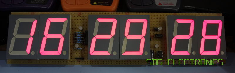
This build is going to be dead accurate as well since he plans to roll in a GPS source. But for now he’s covering the display build itself and will use another clock source IC at first. The display is a set of six 2.3″ 7-segment displays on protoboard. Bonus points for all the tidiness in his point to point soldering!
You may think this is a super simple project, and in a way it is. But [Steve] does an amazing job of dotting all the i’s and crossing all the t’s in a way that is beneficial to learn for all of your prototyping. For instance, he’s combining some 7-segment displays with 5mm LEDs as the colons. He mentions checking the peak wavelength of the displays to match the LEDs when choosing components. The design is also well-planned on graph paper. This may be just for use in illustrating the video but is a great practice in your own prototyping.
We’re not sure if there’s some movie magic involved here as his first burning of code to the PIC microcontroller results in a fully working device — impressive. Looking at his entire presentation, if you follow the workflow that [Steve] uses in his engineering, you’re doing it right!


Nice to see a very solid build done with precision.
I have seen some reuse the decimal point for colon. If the decimal points are towards the right, you can flips the digit after it by 180 degrees and both of the decimal point now forms a colon. The flipped digits have to be driven to account for the rotation.
Nice! I wouldn’t have thought of that.
where is the arduino hidden?
Love that attention to detail. It’s a perfectly executed class project in EE demo/build/prototyping.
This is fantastic! Very, very cool!
GOTTA build your own bench clock. I made a 3d printed gear clock that I love
Where do you buy chunks of perboard that huge? That’s awesome!
It’s made by CIF (cif.fr)- part number AJP58
Where do you buy the pink LEDs?
Just use the right camera and lighting so the display looks pink and washed out!
The SA23-12SRWA display used in this project has a dominant wavelength of 640 nm, which is basically pure red. Incidental light reflecting in the white diffuser may change the apparent color. A red filter would help contrast and color purity.
The camera was saturated slightly by the intense colour from these LEDs. The LEDs are 640-660nm LEDs, so fairly standard deep red.
What’s “swollen” about it? I was expecting something puffy or plumped up… Adjectives, they mean things.
It’s a punne, or humerous play on words, based on the rather large size of the LEDs.
If you can’t figure out the sophomoric humour, one might suggest you’ve been clock-blocked.
Nah.
Damn. Humourous.
“Swollen Clock Build Demostrates…”? “Magnificent Magnifier LED Coversion”? Someone needs a new keyboard, because his/her ‘n’ key is working only intermittently.
I always find it weird when people include the two LEDs between each digit, especially when no behind a bezel. It just seems to have become habitual now, rather than for the reason of separating the digits as they would appear in text. I would love to see a clock use another method for separating the digits. (perhaps a neon-green stripe/box around the digits, or something else which doesn’t naggingly draw electricity?)
A little space would be enough.