A while back, [heypete] needed to get a GPS timing receiver talking to a Raspberry Pi. The receiver only spoke RS-232, and the Pi is TTL level serial. [Pete] picked up a few RS-232 to TTL conversion boards from an online vendor in China. These boards were supposedly based on the Max3232, a wonderchip that converts the TTL serial to the positive and negative voltages of RS-232 serial. The converters worked fine for a few weeks, before failing, passing a bunch of current, and overheating.
On Mouser and Digikey, the Max3232 costs about $1.80 in quantity one, and shipping is extra. You can pick up a ‘Max3232 converter board’ from the usual online marketplaces for seventy five cents with free shipping. Of course the Chinese version is fake. [Pete] had some nitric acid, and decided to compare the die of the real and fake Max3232s.
After desoldering two fake chips from their respective converter boards, and acquiring a legitimate chip straight from Maxim, [Pete] took a look at the chips under the microscope. The laser markings on the fakes are inconsistent, but there was something interesting to be found in the date code markings. It took two to four weeks for the fake chips to be etched with a date code, assembled into a converter board, shipped across the planet, put into [Pete]’s project, run for a little bit, and fail spectacularly. That’s an astonishing display of manufacturing, logistics, and shipping times. Update: The date codes on the fakes had 2013 laser etched on the plastic package, and 2009 on the die. The real chips had a date code just a few weeks before [Pete] decapped them — a remarkably short life but they gave in to a good cause.
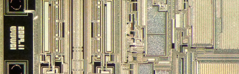
Following the Zeptobars and CCC (PDF) guides to dropping acid, [Pete] turned his problem into solution and took a look at the dies under a microscope. The legitimate die was significantly larger, and the fake dies were identical. The official die used gold bond wires, but the fake ones didn’t.
Unfortunately, [Pete] isn’t an expert in VLSI, chip design, failure analysis, or making semiconductors out of sand. Anything that should be obvious to the layman is not, and [Pete] has no idea why these chips would work for a week, then overheat and fail. If anyone has an idea, hit [Pete] up and drop a note in the comments.


Layman’s guess would be larger size for the authentic chip allowed for better thermal/heat dissipation.
I considered that, but the chips don’t produce any noticeable heat during normal operation. They’re really low-power. They only got (absurdly) hot when they failed.
There is a good chance that the chip died from latch up as they tend to draw a lot of current. Eventually it blows up.
Smaller die means that the chip is built with a smaller geometry. It could be ESD handling as the sellers and shipper don’t usually care about that. It could be the chip doesn’t have good ESD/latchup protection.
I recall an old Analog Devices part (similar to a Maxim) on a $500+ single board computer goes into latch up when the external serial signals are active when the chip powers up. Some how that is what a chip should be able to handle in real life. The Analog Devices rep was telling me that they make Maxim parts and me telling him that shut him up for good.
Latchup happens for surprising reasons: sometimes there’s enough inrush that one of the inputs gets pulled slightly negative, and disaster ensues, sometimes crappy packaging materials induce a charge on a high impedance gate so it can’t shut down, sometimes crappy packaging materials delaminate from the die and pull off a bond wire. And, yeah, if I were trying to cut price, the first thing I’d do is remove all the esd structures while maintaining function to make a smaller chip.
(sorry mods I hit ‘report comment’ intending to hit ‘reply’)
I’m the Pete mentioned in the post. Just for clarity, I have no idea how old the fake chips are or how long it took for them to get put on the boards. The fake chips have 2009-era dates on the silicon and (likely fake) 2013 laser etched marks on the package.
My comment about the 2-4 weeks was in reference to the real chip: it was made only a few weeks before Maxim sent it to me as a sample and I dissolved it a few days later in late 2015. It had a rather short life.
Hi Pete, thanks for letting us know. I’ve used some strikethrough and added an update to the post to fix that part up.
Awesome, thanks!
There are a *lot* of MAX3232-based guys out there, and the ‘real’ MAX3232 is pretty much the stupidly-most expensive one of the bunch (it’s not $1.80 in qty 1, it’s like $3 in qty 1). The cheapest one I know of is either ST Micro’s or Exar’s (ST3232 and SP3232 respectively) which are usually below $0.50 even at qty 1.
But they’re otherwise compatible and of similar performance as the Maxim part?
I have a few of the Exar SP3232’s and they’ve been working just fine for over a year with my GPS receivers. No complaints here. One can get some remarkably compact modules with the SP3232 at https://www.amazon.com/gp/product/B00OPU2QJ4/
The Exar chips are, yeah. The ST chips are 400 kbaud, not 1 Mbaud like the Maxim chips, but you have to be careful, because TI sells a “MAX3232” which is actually only 250 kbaud. So you could buy a MAX3232 that actually isn’t rated the same as the Maxim part.
So what we have here, folks, is a case of “the good, the baud, and the ugly”.
Rob, Rob, Rob… I see what you did there…
When the chips are down, make baud jokes.
TI makes a good substitute as well
And how do we know the date codes aren’t fake?
While a fake date code is certainly possible, there would be no reason to do so. Putting a fake date code in the future would clearly mark it as fake. Putting a fake code a couple of years in the past would have no real advantage; chips do not improve with age like wine or whiskey.
I suspect the date codes just gets copied like the rest of the design. Date codes are there to track issues, but I can imagine it’s not the highest priority when making fakes.
If you look for “new date code” on Ebay a huge number of chips from China will show up. My guess is: they’re fakes or factory rejects and the seller starts selling them around. When someone points out they’re fake and exposes the labeling, the sellers just ask the “fab” to relabel all following lots with a newer/different date code.
hmmm whiskey chips
Fake components are a serious problem that results in countless dollars of damage
i have had a fake level shifter IC i cant remember the origin of blow a $75 FPGA before
Wait’ll your glass cockpit goes dark…
http://mil-embedded.com/articles/counterfeit-components-stakes-rising/
I recently got a batch of fake UDN2981 chips. Never realised it’s worth someone’s while to make fakes of such a basic, basic part… and on the outside, they were faked very well. Not cheap either, and although from China, from a vendor who sent me many good parts in the past.
98% of the chips were fine, 2% were not. One IC actually had no silicon inside.
Taught me to only buy ICs from the well-known places. The point is, a failure rate of 2% means you’re going to learn about your problem the hard way! But also made me wonder – is it worth all that effort for a $0.80 chip? Apparently so.
Your chips may have just been a reel that got swiped and resold before it went through test. A lot of contract test and packaging companies skip probe testing on the wafer, and instead just package all the chips and sort them at final test. For most of our mature processes, that gets you about a 0.5-1% failure rate, and early in the chip fab process we get a lot of empties out of the production line into our verification system.
Interesting! “a reel that got swiped and resold before it went through test”, meaning they might not be fakes but a batch that left the production line illicitly, to a dodgy trader, before testing?
Your description does fit with what I experienced: 2% or less is bad on first test. The others are all good and do not seem to be unreliable or die early.
Seeing as how it at least initially worked and then failed after a week of use I’d suspect electromigration. Basically some of the internal metal lines fused open due to not being sized large enough to supply the current. I’m purely speculating here but my hunch is that since the frauds were smaller than the original maybe it was just a cheap reverse engineering job. Go ask AMD how they reverse engineered the x86 instruction set back in the day… It wouldn’t be too difficult for a crude and cheap chinese fab to simply de-process the original layer by layer and copy the metal routes. Then go find a suitable process node that is cheap and duplicate the design. But if you fail to actually understand your transistor drive strengths for the process node being used they could be pushing much more current than the original layout was designed for and then you fuse open a metal line. It would be interesting to maybe characterize the I/V curves of the an output of this device. Even doing a simple open/short testing of all pins on the bad part could help narrow down root cause.
With that all said looking at the pictures of the bare silicon for the fraud and the real parts – the fraud doesn’t look like an exact photo copy. They may very well still have copied the schematics from reverse engineering, and if they don’t have a good engineer who understands layout then an inexperience layout person can just take the schematic and draw something that passes LVS and DRC but will not work once power is on (or in this case not work for long).
Another possibility is that if they didn’t use gold bond wires and the original design was built for gold bond wires then using copper bond wires could cause cracks internally that show up as resistive shorts which quickly fail over time.
As for ESD damage – in my experience ESD damage doesn’t result in a “walking wounded”. It generally fuses metal open or short and results in a bad part from time 0. But I suppose it’s possible that an ESD event caused a problem that only exacerbated itself after a few power cycles and use.
AMD didn’t need to reverse engineer x86. They were the second source manufacturer.
https://en.wikipedia.org/wiki/Advanced_Micro_Devices#First_twelve_years
>In 1981, IBM created its PC, and wanted Intel’s x86 processors, but only under the condition that Intel also provide a second-source manufacturer for its patented x86 microprocessors.[16] Intel and AMD entered into a 10-year technology exchange agreement,
Looking at the depackaged part pics it’s clear that the fraudulent chips are not simply photo copy and shrinks from the original. That said I still suspect an electromigration issue. If too much current flows through a wire not sized to handle it then it slowly pulls the metal away to the point that the metal is no longer there and you have an open. It’s basically a fuse.
Someone could deprocess the original chip layer by layer and reverse engineer the entire chip (just ask AMD how they did it with Intel parts – https://en.wikipedia.org/wiki/AMD_Am9080). Then go find a cheap process node and re-layout the entire circuit. Now the problem is that an engineer who doesn’t understand layout will not be able to properly review the layout for potential electromigration issues. And the cheap layout person for this copy very likely doesn’t understand electromigration. One could easily generate a layout that is LVS/DRC clean but will fail once powered up or will fail soon after power up due to electromigration.
Another potential failure point is the switch from gold to copper bond wires. If copper bondwires were used and created cracks inside the die that could result in resistive current paths that ultimately failed.
It would be interesting to open/short test the failed parts and then possibly curve trace the bad pins to further debug the failure mechanism.
They could have a thermal test and sort the fakes accordingly, which would ensure that the cheapest ones were the ones most likely to fail soonest. That would be a test worth trying on a few samples from different sources, see what temperature they run at and if it correlates with cost and lifespan.
Both the bond wires and the Al bond pads were etched during decap, not normal with fuming Nitric. The Al metal leading from the bond pad next to 2009.11 marker looks open, can not be certain with this photo. My guess would be latchup induced overstress of this metal trace. Looking at the die layout, the output and input xsistors are packed together compared to the Max232 die which can make a die easier to latchup. The fact that the device got really hot when they failed would also indicate latchup.
Could they possibly have used copper bond wires? Copper bond wires often use ball bonding and dissolve in nitric acid (I used ordinary nitric acid, not fuming), according to what I’ve read.
Maybe I missed it.
Were the parts, as packaged, being mis-represented as being manufactured by Maxim? Did the die photos have a Maxim logo? Did the package have the Maxim logo?
Or were the parts being sold as compatible with the Maxim part (like of lot of industry standard parts). And using the same Maxim part number.
In the later case, that’s just a marginal vendor with a Maxim-compatible part, that didn’t really meet the stringent Maxim specs. And it failed accordingly. (You get what you paid for.)
Did the parts fail after a few months from simply being powered on for a period of time in a well-controlled environment?
…OR…
Did the parts fail in actual use where you’d have to investigate ESD spikes, ground problems, power supply transients, etc. It’s possible the parts actually meet spec, but were abused. It’s possible that similar Maxim parts survived the same abuse. These parts interface to the outside world…lots of opportunity for abuse.
If the parts were being mis-represented as genunine Maxim parts (but weren’t) then I’d think Maxim would like to know more about where they came from.
The product listing, such as it was on DealExtreme, didn’t explicitly say that they were using “Maxim”-brand chips, though they did specifically say “MAX3232”. I read that as claiming that they were using real MAX3232 chips which are made by either Maxim or TI. This obviously wasn’t the case and, as you say, you get what you pay for.
The package, as picture on my site shows, said “MAX3232” on it. It did not include the Maxim logo, though to be fair, neither did the authentic Maxim chips.
One could argue that absent any direct claims to being a “Maxim” chip, these chips are neither “fake” nor “counterfeit”, though I would disagree with that assertion. Had they claimed that they were “MAX3232-compatible”, that’d be one thing, but claiming they’re “MAX3232” chips (which are not a generic industry identifier, like generic 74-series logic) while they are clearly not is deceptive.
In regards to how they were used, they weren’t used in a lab-grade environment with all variables known and controlled. They were used in a typical household environment with normal temperature changes, etc. Since each module was connected to a GPS timing receiver, I didn’t handle them after their installation (except to investigate their failures), they had good power supplies with good grounding, etc. The GPS receiver has a real, older MAX232 internally and it continues to work just fine even after the two “fake” ones to which it was connected had failed.
After the fake chips failed, I desoldered them from the interface board they came installed on and replaced them with genuine Maxim MAX3232s. These have been working for nearly a year with no problems whatsoever in the same environment. Other chips like the Exar SP3232 interface chips I use with other, similar devices in the same environment have also been working for years with no issues. Only the fake MAX3232s failed.
I did inform Maxim, as they solicit such reports, and provided them with all the details, die photos, package photos, etc. they requested. I have no idea what happened after that.
Just FYI, a reputable manufacturer recently sent me a PCN. It informed me that a chip they had been making using aluminum bond wires was going to be made in the future with silver bond wires…. So even “high quality, western” chips will have aluminum bond wires. This dissolves in anything but ph-7 water.
In the cases of “fake chips”, I often see people noticing small differences and then blowing things up to: see they used inferior materials. They used DIFFERENT materials.
As to this specific case, would it be possible that these fake max3232 chips are other-brand max-232 compatible chips. They work (at first), but die (soon), at 3.3V.
For clarity, my mention of the non-gold bond wires wasn’t meant to imply that chips using non-gold wires or materials different from a particular chip are somehow inferior. It was simply meant to compare-and-contrast the genuine and fake chips in my particular example and to make it clear that I did not physically pull off the bond wires on the fake chips.
It’s certainly possible that these fake MAX3232 chips are re-branded MAX232 (or other similar) chips, but all the second-source companies for MAX232s include their logo and/or brand name on the metal layer and I recognize most of them (e.g. Maxim, TI, etc.). I don’t recognize the markings on these fake MAX3232 dies. Even then, the output voltages of the fake chips better matched those of the real MAX3232, and not that of a MAX232 running at 3.3V (I tested this with a real MAX232), so it seems likely they were meant specifically to mimic the real MAX3232.
That said, I’m really curious if anyone can identify the manufacturer and original name/brand/type of the chips in question.
3.3 V is “TTL level”?
Apologies: I meant “TTL-polarity” (e.g. 0-5V, 0-3.3V, etc.), as opposed to RS-232 polarity (-15V to +15V).
Read AN218 from EXAR to prevend latch-up.