
Down the rabbit hole you go.
In my particular case I am testing a new output matching transformer design for an audio preamplifier and using one of my go to driver circuit designs. Very stable, and very reliable. Wack it together and off you go to test and measurement land without a care in the world. This particular transformer is designed to be driven with a class A amplifier operating at 48 volts in a pro audio setting where you turn the knobs with your pinky in the air sort of thing. Extra points if you can find some sort of long out of production parts to throw in there for audiophile cred, and I want some of that.
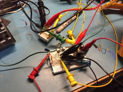 Lets use some cool retro transistors! I merrily go along for hours designing away. Carefully balancing the current of the long tailed pair input. Picking just the right collector power resistor and capacitor value to drive the transformer. Calculating the negative feedback circuit for proper low frequency cutoff and high frequency stability, and into the breadboard the parts go — jumper clips, meter probes, and test leads abound — a truly joyful event.
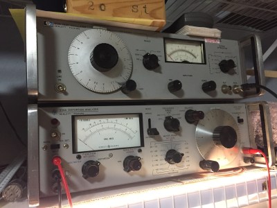
All of the voltages check out, frequency response is what you would expect, and a slight tweak to the feedback look brought everything right into happiness. Time to fire up the trusty old HP 334A Distortion Analyzer. Those old machines require you to calibrate the input circuit and the volt meter, tune a filter to the fundamental frequency you are applying to the device under test and step down to lower and lower orders of distortion levels until the meter happily sits somewhere in the middle of a range.
Most modern circuits in even cheap products just go right down to sub .1% total harmonic distortion levels without even a thought and I expected this to be much the same. The look of horror must have been pronounced on my face when the distortion level of my precious circuit was something more akin to a clock radio! A frantic search began. Was it a bad jumper, or a dirty lead in the breadboard, or an unseated component? Was my function generator in some state of disrepair? Is the Stephen King story Maximum Overdrive coming true and my bench is going to eat me alive? All distinct possibilities in this state of panic.
After a little break, as the panic and need to find an exact singular problem began to fade I realized something. It was doing exactly what it was supposed to be doing.
 The input part of choice in this case is a mostly forgotten 60’s Hitachi PNP silicon part 2SA565 in a (here comes the audiophile cred as we speak) TO-1 package with the long leads so perfect for point to point assembly. (More on this aspect for another time.) After all, these parts adorned the audio stages of countless Japanese radios and such. A PNP small signal BJT is as good as any right? Also these surplus store caps and resistors are perfectly good. They all measure out ‘good’ on the meter after all. These jumper leads and meter probes are Pomona. Best you can get. No worries there. And on and on the excuses and rationalizations come.
By this point no amount of optimism or delusion could really help. The grown up hiding inside my head spoke up and the truth was obvious. How could a pile of old noisy parts and wiring more like spaghetti than a proper electronic device do any better? I am trying to reach orbit with a bottle rocket of my own design. I lost perspective. So eager to test my new widget that I completely neglected to take good scientific practices into account on the faith that previous experience could guide me through lack of proper setup and experimental control. Just the crosstalk on those jumpers and probes could account for this problem, not to mention noisy out of spec old parts.
It literally could be impossible to ever find all of the possible causes. I built failure in from the start just for the sake of having something that used parts nutcase audiophiles would find more visually appealing. I better go find out where I lost my integrity on this one. Perhaps I set it down with my wallet and keys when I got home from work today. I think I will go clean my bench and layout a PCB with new modern components so I can actually get this test done.
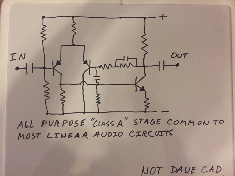
This is a standard long tail pair input circuit used in most linear audio designs. A very handy thing to be familiar with as it is extremely linear and adaptable. Shown here in its standard audio configuration including high frequency shelving for high frequency stability and low pass filter for DC drift reduction.


You can make mistakes, screw stuff up and generally suffer from PEBKAC’s of a frightening variety. You only fail if you quit.
EXACTLY! It’s like the old adage,”If, and when you fall, you just pick yourself up and try, try again.” If we had quit at our early stages of development, we would be on our hands and knees everyday. Ohh…and for those who don’t know about PEBKAC, then I suppose the problem exists between the keyboard and chair. Merry Christmachanukwanzaaka to all.
I did build a clean version with proper components and it worked fine. The failure was more of a nature of the methodology. Not the actual thing I was trying to do. Everybody needs a little reminder every now and then. Cautionary tales and such. Glad you liked it.
Engieering practices, not scientfic practices.
You actually think those two things are separate?
II would try the same circuit on a nice tight PC board without the foot long clip leads. Shielded cables for signal, and good power decoupling at the board. I have seen many lab tests (usually my own) give poor results for poor setup.
There’s probably an audiophile somewhere who would use even with the distortion, or possibly because of it. Just gotta market it as a feature ;)
High fidelity distortion, make everything sound like a fresh shiny electric guitar in the fresh cool ocean breeze. No that’s HiFi (TM)
Sorry, couldn’t resist ;)
My “W” had a crumb under it, should be “Now that’s….”
Pieces of the story are missing. How much distortion? Did something explode? **If it works it is good**(tm). I made an output audio stage with a single transistor and the power transformer (yeah, 60 Hz – oh the horror!) output last year, and the level of distortion is quite imperceptible to my ear. It sounds quite good.
I agree. I was very surprised the article just ended like that. This story reads to me as this: “I soldered up a circuit, it didn’t work as I expected, oh it must have been how I assembled it, I will change it in the future. The end”.
Obviously you used components that are too modern. Try some WWII surplus tubes.
or snap up some Soviet era mil spec tubes while they’re still reasonable. I bought several a couple of years back when they were cheap like borscht.
In an era where electronics means hooking up a sensor that already does everything to a microcontroller, it’s refreshing to see someone go down to the transistor level. Keep those articles coming ;)
Please make the same circuit with the same parts but layed out properly, and show us the difference in part two. Then use higher quality replacement parts in the same new layout and show the improvement again.
Already working on it. I am doing it on vero board first. Being the holidays it may take me a while to complete.