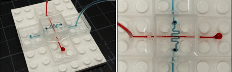
Years ago, prototyping microfluidic systems was a long, time-intensive task. With inspiration from DIY PCB fabrication techniques, that time is now greatly reduced. However, even with the improvements, it still takes a full day to go from an idea to a tangible implementation. However, progress creeps in this petty pace from day to day, and in accordance, a group of researchers have found a way to use 3D printed molds to create microfluidic LEGO bricks that make microfluidic prototyping child’s play.
For the uninitiated, microfluidics is the study and manipulation of very small volumes of water, usually a millionth of a liter and smaller (nL-pL). Interestingly, the behavior of fluids at small scales differs greatly from its larger scale brethren in many key ways. This difference is due to the larger role surface tension, energy dissipation, and fluidic resistance play when distances and volumes are minimized.
By using 3D printed molds to create microfluidic bricks that fit together like LEGOs, the researchers hope to facilitate medical research. Even though much research relies on precise manipulation of minuscule amounts of liquid, most researchers pipette by hand (or occasionally by robot), introducing a high level of human error. Additionally, rather than needing multiple expensive micropipettes, a DIY biohacker only needs PDMS (a silicon-based chemical already used microfluidics) and 3D printed molds to get started in prototyping biological circuits. However, if you prefer a more, ahem, fluid solution, we’ve got you covered.
[via Adafruit]


No mention of the paper behind a pay wall? With that stroke, you’ve consumed my waking day.
http://iopscience.iop.org.sci-hub.cc/0960-1317/27/3/035004/
I apologize, I’m at a university and the paywall is automatically bypassed. In the future, I will make sure to check on a regular network. Thank you for pointing this out, as I probably would not have noticed otherwise.
“A truly Lego®-like modular microfluidics platform” filetype:pdf
https://pdfs.semanticscholar.org/752b/60c4f31c4838153e3773728de663fc71c1ea.pdf
My Dearest….
:)
There is a thing called “Scihub”.
It real is like LEGO !
Dealing with fluids in small bore tubing is a an interesting challenge – it seems time like going up the tube rather than flowing down.
And were did you get the story from.
And what is this that they want me to download?
hum .. “creeps in this petty pace from day to day, ..” .. reading Shakespeare lately ?
I didn’t realize this was Shakespeare! I recognized the line from Hamilton’s “Take a break” and then couldn’t stop reading the article to the tune of the song.
So how do they align the tiny channels between adjacent bricks? Lego pieces have a tiny amount of give and when you’re dealing with channels that tiny that’s going to be an issue. Also how do they maintain a seal for that matter?
I suspect the PDMS might have the kind of sealing properties needed. Like how o-rings are sometimes made out of silicone.
JRDM is right, the inherent properties of PDMS are what allow the blocks to seal against eachother. They use channels on the bottom and lateral surface of the blocks. On the lateral surface, they key male and female and allow 20-200um overlap on the interface to get a tight seal.
I have to think in this direction: https://en.wikipedia.org/wiki/Fluidics
There was a bunch of things like these during the USSR times.
Here’s a picture of a discrete module that performs a simple logic operation like AND or OR. One would use a router to make connecting channels in a backplane, then stick these modules in a backlpane to make a simple computer. Oh yes, these are digital BTW and there were different things from logic gates to triggers.
http://www.ngpedia.ru/pic/053fXfd0c962z47935E80014260516.png
Unfortunately, you have to hunt for scraps of info about these things.
Fluidic Programmable Gate Array. ;-)
My fluidic CPU is over pressured to 30psi, I can almost run doom. LOL
Having only moderate biochemical lab experience and no experience in microfluidics, I always wonder how this is actually useful. I mean, yes, they can let small amounts of liquid flow through a couple of fancy channels, but how do you use that, for example, to reduce pipetting in a PCR reaction?
I would like to know the possible uses of this outside a lab, it would be fun to screw around with fluids on my bench. I’m wracking my brain for an excuse to play around with elaborate runs of tubing filled with colored liquids.
Start here:
https://en.wikipedia.org/wiki/Microarray
(Those (micro)beasts have to be fed & groomed, after all)
Enjoy :-)
Try to build a simple computer out of pure fluidic logic. There are ways to make logic gates from “pure fluidic amplifiers”, in essence transistors which work without mechanical parts by using the coanda effect. I have found it notoriously difficult to tease detailed information on this technology out of the internet. Apparently nobody in the dyi scene has demonstrated a working setup of multiple gates.
I’ve been playing with an interactive 2D fluid simulation, and so far I have figured out how to create flip flops, but I haven’t succeeded in connecting them.
At least for this kind of work, PDMS casting is unnecessary and direct printing of the devices should work well enough.
There are Soviet books about these systems and there even was a set of pneumatic thingies that worked like 7400 logic chips. Like a microchip, but cast out of plastic. You could connect them via tubes or plug them in a backboard with inteconnecting tubes cut out with a router.
I have tried to find a list of them, but it looks like the only way is looking for a bunch if old books in a library and that starts a whole bunch of problems from finding out which books I need and getting a copy of them smuggled out.
I think I figured out the basics, like what general shape the components have to be. I think the 2D simulation route is the best way forward for now. Even with the help of these books any diy design would have to be iterated until it works.
The 3D printed versions would have to be arranged in a 2D fashion anyway, both because of how printers work and to have any clue about what’s going on inside. From my simulations so far, the shape of the components isn’t even the main problem. I think my main problems so far are the resistance and the backpressure of the output connections. That’s why I need a more sophisticated simulation.
Came here looking for an excuse to buy the big bucket of Lego blocks I’ve been wanting. Disappointed…