If you were not aware, LEDs can also work in reverse: they deliver tiny amounts of current, in the microamp range, when illuminated. If you look on YouTube you can find several videos of solar panels built with arrays of LEDs, but powering an electric motor with a single 3 mm LED is something that we’ve never seen before. [Slider2732] built a small electric motor that happily runs from a green LED in sunlight.
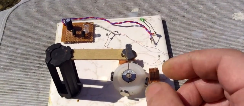
The motor uses four coils of 1,000 ohms each. Using coils with many turns of very fine wire helps to draw less current while keeping an appropriate magnetic field for the motor to run. To keep friction at a minimum, the rotor uses a needle that hangs from a magnet. Four neodymium magnets around the rotor are periodically pushed by the coils, generating rotation. A simple two-transistor circuit takes care of the synchronization and yes, the motor does run on the four microamps provided by the LED, and runs pretty well.
Building motors is definitely an enjoyable activity, these small pulse motors can be built in just a couple of hours. You can use coils with just a few tens of turns which are much more easy to make but of course you will need something more than four microamps! The nice part of making an ultralow current motor like this is that it can run for a very long time on a tiny battery or even a capacitor, we invite you to try building one.


I would have preferred if he had covered the LED to stop the motor, to demonstrate that it was the actual power source.
Agreed
Agreed also but I do believe the video, The motor had no load and he wasn’t claiming overunity like countless others on youtube.
I call bull. According to his paper he shows in the video he gets 4µA from the LED driven in “generator” mode @ 1.4V. So that LED is outputting 5.6 µW. Let’s say the motor is 100% efficient, for argument sake.
There’s no way that 5.6 uW is enough for all the “parasitical” powers such as:
wind resistance / wind friction, whatever you want to call it
cable resistance (1k in the coil)
shaft resistance turning around bearing and other friction
I bet 5 bucks that the white plate that everything stands on has a coil inside of it and under the table there’s another coil which works like a transformer and pumps energy into the system.
Because lookie lookie, he _never_ covers the green LED to prove that it’s where the energy comes from. He never moves the white plate around.
If anyone had done something impressive like that I’d be holding it in my hand and trying my best at proving that it was the real thing. This guy is not even close at trying, he’s doing his best at trying to trick every viewer for views and likes.
Obvious bullshitter is obvious.
Aerodynamic losses.
And I see a capacitor on the board…
There is a solar cell on the schematic that’s not present in the video. So the schematic is wrong, or the solar cell is hidden somewhere. The large capacitor is present in the schematic. I think that the initial manual spin might have built up a substantial charge on that capacitor and the energy was being released into the motor later. Anyway, I don’t think that this is BS but I do think something is going on that makes our instincts feel like something is “wrong” here.
Even easier, rotating magnet under the table, works like a magnetic stirrer.
Or just a button cell under the PCB
The way the motor turns and stalls, I’d guess the drive circuit he shows is actually running it, but with a battery somewhere.
5.6 µW is such a small current that the loss in the resistances would be neglible. The ohmic loss is proportional to I^2 R and the current at 1.4 volts would be 4e-6 Amps, so a 1 kOhm resistor would only dissapate 16 nanoWatts or 0.3% of the available power.
>”shaft resistance turning around bearing and other friction”
It’s pivoted on a magnetically suspended needle, much like a compass bearing, or resembing a mechanical watch bearing. There is practically no friction.
There’s friction from the air, and there’s resistance from the eddy currents as the magnets pass the coils.
Drag is proportional to v^2, unlike dry friction. The rotor is moving pretty slowly, so aerodynamic drag will also be pretty tiny.
I’ll take that bet.
5 bucks.
Signify your assent in a reply to this comment, and I’ll provision a disposable email that I’ll disclose in a reply to you in this forum, and we can take it private to work out terms.
It’ll be fun.
Complete bullshit
Can hear the field through the mic.
Much tiled wow
I noticed the sound as well and what that was… makes sense
UV eraseable EPROM chips can be used as tiny solar cells. Daisy chain the GND and VCC pins, expose to sunlight.
Do they need to be non-blank for that? I mean, is that a photoelectric effect on illuminated PN junctions, or is it recovery of charge buried in memory cells’ MOSFET gates?
Hmmmm must investigate, sounds like a conflation with decapped DRAM.
Decapped DRAM can be used as a monochrome camera since light shorts the (photo)transistors of the transistor-capacitor groups that form the bits. But you’ll have to add some optics and figure out how bytes are laid out on the die to turn a dump file into a picture.
The first electronic camera was made with one of these chips.
Yah, but I thought they’d work more like the LED if the emitter side is open.
I think the idea with the DRAM camera is to charge all the cells up (so, set them to “1” then), then let light destroy the charge, which is what it tends to do.
EPROMs I suppose you could try make a long-exposure camera from. Don’t EPROMs turn from 0 to 1 in UV light? Their default state is 1, and programming produces a 0? Although that said, programming uses (well, back in the days of EPROMs) 21V, so presumably that means the discharged state is their default. Does that mean that logical “0” is actually charged-cell, and logical “1” is discharged-cell? Because I’m pretty sure a blank EPROM is all FFs.
Would an EPROM work as a solar panel? I dunno. I can imagine on first thought it might. But then EPROM cells aren’t really conductive are they? They’re supposed to have an insulated region that a charge stays on, that affects a nearby FET’s gate, which is how they’re read without removing the charge. Then to program them you blast 21V and that cuts through the insulation. Far as I know, that doesn’t involve quantum effects, but I think EEPROM does. The 21V blasting is why they have a limited number of programming cycles.
So maybe EPROMs won’t make a solar panel. If I had one nearby I’d go check it out, but there hasn’t been an EPROM in my house for a few years, now.
As far as DRAM, probably should work as a solar panel. Not sure on the details though, now. Since does a FET have the right structure of junctions to act like a solar cell? Solar cells are basically diodes. And in practice they are, and diodes are solar cells too.
While I’m asking silly questions, does the forward voltage of an LED correspond to what colour it’s supposed to emit? Not as in being variable, but as in blue LEDs taking a higher voltage than red or green. Though red and green have pretty much the same voltage. So hmmm. Does that mean a 1N4001 emits some invisible light, inside it’s little package? Mind, you’d surely notice that effect from all the small glass-bodied diodes. So “no” is prob the answer.
Great description here:
https://www.youtube.com/watch?v=Wduw_a3AL10
What’s that dirty big clear 5mm LED doing on the PCB? What’s it for?
Also, call me crazy here, but does the 3mm green look like it’s giving off light? Like it’s plugged into power? Surely nobody would be daft enough to actually wire up a pretend generator like that.
It does seem unlikely. But then again, if it’s well-balanced, under no load, and we’ve no idea how fast it’s actually going, it could perhaps be working from just about zero power. It would be so easy for him to cover up the LED just to prove the point. And also make an effort to eliminate hiding places, so we can see everything there is, in the video.
Not calling him a fake, but I can see room for doubt. Wouldn’t take much for him to eliminate most of that. Most reasonable doubt, that is. He could still have a gigantic coil in the cellar underneath him, running on kilovolts. I don’t expect him to do it in the vacuum of space, miles from anywhere, and a wide-angle lens just to show nobody off-screen is helping him.
The capacitor on the board could store some energy. Not too much, you’d think, for running a motor on. But a few seconds’ worth of what you could suck out of an LED solar cell.
Actually another thought… Crookes radiometer. Works on basically no power at all, and spins round pretty fast. With just about zero load. A Crookes is in a vacuum, but has vanes. This thingy here isn’t, but doesn’t. So probabaly balances out more or less, give it an order of magnitude or two.
So this might be a demonstration of the fact you can power a motor on almost nothing, if you balance and design it very gently. As well as the fact that an enormous ball of atomic fusion millions of times bigger than the world, can shed enough energy over 3mm(sq) x pi / 4. So, 9 x pi / 4, or 2.25 x pi, or about 7 square mm. To power a tiny motor.
Working out a 3mm circle as a percentage of the Sun’s entire surface (and output power) is left as an exercise from the reader. The 3mm can be considered to be on the surface of the Sun itself, or somewhere within the Earth’s orbit. Or up a dog’s bum for all I care.
A Crooke’s radiometer will not work in a complete vacuum. A modicum of air is *required* for its operation (not too much, though, but not for reasons of drag).
A thousand watts per square meter is the number you’re looking for.That’s the solar power available at the surface of the earth with no more than 1.5 air masses (the amount of air that the sunlight has to travel through at zenith). Then there’s the conversion efficiency of the diode (probably about 15%). I come up with about 0.00106 watts.
Conservation of energy:
1. 4 magnets, 1 cm distance (not taking into account the disk), assuming 1g / magnet (ee e.g. https://www.kjmagnetics.com) momentum of inertia=4*0.001*0.01*0.01=4e-7 kg*m^2
2. Kinetic energy of the motor rotating at 5 rps: K=1/2*I*w^2=2e-7*2*3.14*2*3.14*25=2e-4 kg*m*m/s2
3. Roughly, power needed to make it rotating from zero to 5rps is equal to energy/time, assuming it takes 5 sec:
P=(2e-4/5)=40 uW
which is ~10 times more than claimed 6 uW.
Joule heat is much smaller : Q=i^2*r=4uA*4uA*2000 Om=0.03 uW
On the other hand numbers (40 uW) are very close to the claimed 6 uW, taking into account roughness of this estimation, if magnets are a little bit lighter, if rotation frequency is lower, if actual current is slightly higher than this is possible.
I do believe this is not a scam. This type of motors is almost frictionless.
Very astute.
I note that that he bump-started the armature.
After it’s spun up, all it has to do is overcome friction.
This is a real motor, but it is NOT being powered by the green LED. The operation of the circuit is being misrepresented by the video from Slider2732. Check out his own referenced link to Lidmotor’s video in the youtube link. The schematic that Slider2732 shows in his video is virtually identical to Lidmotor’s. The “capacitor” shown in both versions of the schematic *is* the power source – Lidmotor uses a supercapacitor that he charges up to run the motor, while Slider2732 shows a “6V solar cell” on his schematic, but it’s not present in the build. I am assuming Slider2732 has charged up his capacitor with some other power source. Also, the green LED is *supposed* to be lit when the motor is running – again, check out Lidmotor’s video to see the LED turn off when the motor is stopped and light up again when the motor runs. Slider2732 is doing something weird here too – when he stops his motor, the LED stays lit. The green LED is definitely not powering the motor.
Talking about generating power with a diode, ever tried using a camera flash on a modern laptop screen? It will generate enough power to blow the screen control circuitry.