For anyone with interest in electric vehicles, especially drives and control systems for EV’s, the Endless-Sphere forum is the place to frequent. It’s full of some amazing projects covering electric skateboards to cars and everything in between. [Marcos Chaparro] recently posted details of his controller project — the VESC-controller, an open source controller capable of driving motors up to 200 hp.
[Marcos]’s controller is a fork of the VESC by [Benjamin Vedder] who has an almost cult following among the forum for “creating something that all DIY electric skateboard builders have been longing for, an open source, highly programmable, high voltage, reliable speed controller to use in DIY eboard projects”. We’ve covered several VESC projects here at Hackaday.
 While [Vedder]’s controller is aimed at low power applications such as skate board motors, [Marcos]’s version amps it up several notches. It uses 600 V 600 A IGBT modules and 460 A current sensors capable of powering BLDC motors up to 150 kW. Since the control logic is seperated from the gate drivers and IGBT’s, it’s possible to adapt it for high power applications. All design files are available on the Github repository. The feature list of this amazing build is so long, it’s best to head over to the forum to check out the nitty-gritty details. And [Marcos] is already thinking about removing all the analog sensing in favour of using voltage and current sensors with digital outputs for the next revision. He reckons using a FPGA plus flash memory can replace a big chunk of the analog parts from the bill of materials. This would eliminate tolerance, drift and noise issues associated with the analog parts.
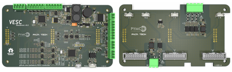
[Marcos] is also working on refining a reference design for a power interface board that includes gate drivers, power mosfets, DC link and differential voltage/current sensing. Design files for this interface board are available from his GitHub repo too. According to [Marcos], with better sensors and a beefier power stage, the same control board should work for motors in excess of 500 hp. Check out the video after the break showing the VESC-controller being put through its paces for an initial trial.


Awesome! This is enough to control the motor for an electric motorcycle. Looking forward to the more powerful versions. :)
I’d say it’s way overkill for a motorbike :D
Naah, it’s just a bit more powerful than the http://lightningmotorcycle.com/product/specifications/ e-motorbike .
150kW is of course on the high end of the power range for a motorbike, but such bikes (gas powered) exist.
But you don’t get the mountain of torque until the piston engine reaches high RPMs… with an electric one, you get everything the drivetrain can dish out pretty much from 0 speed, rather scary ;-)
Degloved while riding an Ebike, we used to get all those types of videos at Toolbox mostly involved lathes mills and presses
Wow, that’s really powerful! Thanks for sharing.
Great work! And most important, open source :D
Awsome work with FPGA replacing all analog parts:
https://endless-sphere.com/forums/download/file.php?id=219890&sid=17733bcd6fefa29dd5bf9be6d5a75bae
For anyone wondering: the original VESC suffers from some fairly serious problems, most of them packaging-related. The specs are great, but in reality, the MOSFETs overheat because there is no easy way to cool them effectively, and the filter capacitors are hanging in the breeze, so there are mechanical issues there.
A couple of groups have produced far superior hardware designs. Don’t buy the original unless your continuous power requirements are low and you have some way to handle mechanically supporting the caps.
Check out the latest official vesc 6.xx, its miles ahead of the previous v4.xx
Not to mention waaaay more expensive
200 hp = 149.14kW
500 hp = 372.85kW
In this case the power is mostly related to the transistors and DC link you use. This brain board can be connected to a 5kw to 200kw power pass, limited by the noise in the analog sensing. Going fully digital I’d say it becomes a 400kw capable system, and it starts by testing this current sensor https://endless-sphere.com/forums/viewtopic.php?f=30&t=89911&start=25#p1316043
I just lack a competent motor for going further.
It is great work, and provides us with a fine path to making horseshoes for when we get a horse one day.
But economical 20 – 100 hp motors are unobtanium. Perhaps we have to wait for scrapyards to fill with obsolete and bingled EVs.
For a motorbike that power range would be OK, for a car I would prefer more power, like the 125kW/160hp of my gas powered car.
400hp engines were also unobtanium at some point history, now its pretty easy to get one. Same thing will happen with electrics, sooner than later you will find motors everywhere.
Here
https://endless-sphere.com/forums/viewtopic.php?f=30&t=89056
So hoping they or someone else picks up the ball on producing the controller boards. I understand what’s involved, just not equipped to do it for a one off. I’d totally pay $150 within the next month for the driver board and source my own IGBTs and gate drivers. Have the perfect heatsinks too, thanks old Antminers ;)
Seriously though. I cant be the only one thinking this. Have a project in progress that it’d go GREAT with.
Maybe after the next pcb revision =)
relevantish to anyone interested in DIY/open cource 3 phase drivers but damian Maguire has been wandering down the road of building an open source controller board for the tesla high current driver stages.
https://www.youtube.com/user/pooey1911
I would be happy if HackADay could feature/talk about our OpenSource firmware for chinese dirty cheap $14 EBike motor controllers: https://opensourceebikefirmware.bitbucket.io/
Recently we go a milestone of understanding and implementing very low resolution FOC on this motor controllers that use a STM8 8bits 16MHz microcontroller: https://opensourceebikefirmware.bitbucket.io/Various–Endless-sphere.com_forum_messages–2017.09.02_-_How_to_do_FOC_on_the_BMSBattery_S06S-Kunteng_STM8_motor_controllers.html
If you want hackaday to feature your work then simply submit it using the link in the menu, this would be preferable to self inserting into the comment section of someone else’s work.
Battery or ultra capacitors to power this equipment?
I guess batteries are still bottleneck of ev adoption.
Yes, you are exactly right mr.Ahivko, I just agree with you. I had some confusion but now I am sure about that. Thank you.
The battery in the video is lithium titanate, custom made, 8C charge rate =)
Kudos to Marcos for bringing bad-ass power electronics to Hackaday. We, in my group, are moving towards digital signals (simple PWM so far) for current and voltage sensing because of distance and because of the number of signals we need to measure. Or perhaps that’s a poor excuse and the only issues is that we don’t know much about high frequency and analogue electronics and are lazy to design proper wiring and instrumentation stuff to do things properly. We also use fiberoptics when we want to go posh and we have big distances between the IGBT drivers and the control board but I’m sure one can do better with twisted pair wiring. Exciting times.
Thanks! Here is a high performance approach to digital sensing
https://endless-sphere.com/forums/viewtopic.php?f=30&t=89911&sid=64927cf75ac8086bff89df2bc0b31cf2&start=25#p1316043
A 20Mhz pwm makes it easier to filter while keeping a fast step response.
It’s really nice to control the motor. It’s enough now :). Can you tell me about the power equipment? Everything is nice.
Really nice project! Aside from the EV application would it be possible to drive industrial async motors and servos with it? I mean from the mains just like a traditional frequency converter? I’m not great with Kicad, couldn’t open the scematics properly.
I think the firmware doesn’t support induction motors yet, no V/f control loop. I know benjamin is working on it, so far there is an open loop FOC that lets you set a fixed sine frequency.
I don’t think there is servo support though.
Try kicad nighties, I used the bleeding edge to get this board done
Thanks for the quick reply! What’s in mind is a showcase board to demo a simple frequency converter without complete functions. I think your board would already be an overkill for that. Keep up the good work, the EV business is rising with full speed.
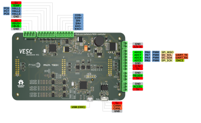
How do I connect this to an actual Motor from the U V W Banks to the 3-Wire Motor Input Cables ?
Through a GATE Driver Circuit ? If Yes, can I have the Schematic Diagram of the same.
The Open Source High Power EV Motor Controller delivers customizable, high-performance control for electric vehicles, fostering innovation and reducing costs.