In a departure from his usual repair and tear down fare, [Kerry Wong] has set out on a long-term project — building a whole-house battery bank. From the first look at the project, this will be one to watch.
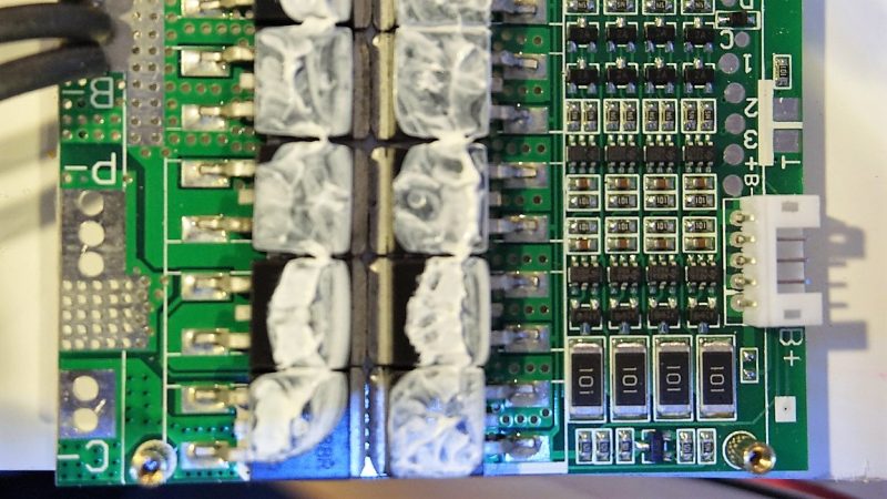
To be fair, [Kerry] gave us a tease at this project a few months back with his DIY spot welder for battery tabs. Since then, he appears to have made a few crucial design decisions, not least of which is battery chemistry. Most battery banks designed for an inverter with enough power to run household appliances rely on lead-acid batteries, although lithium-ion has certainly made some inroads. [Kerry] is looking to run a fairly small 1000-watt inverter, and his analysis led him to lithium-iron cells. The video below shows what happens when an eBay pack of 80 32650 LiFePo4 cells meets his spot welder. But then the problem becomes one of sourcing a battery management system that’s up to the charge and discharge specs of his 4s battery pack. We won’t spoil the surprise for you, but suffice it to say that [Kerry] really lucked out that only minimal modifications were needed for his $9 off-the-shelf BMS module.
We’re looking forward to seeing where this build goes, not least because we’d like to build something similar too. For a more traditional AGM-based battery bank, check out this nicely-engineered solar-charged system.


Cool, looks like a fun power electronics project. How d’you balance the voltage of individual cells to prolong their lives when the anodes and cathodes are all in parallel like that?
The lower voltage cell in the parallel config will kick off Kirchhoff’s law and demand a recharge from it’s neighbors.
This sounds so funny and wrong, but I guess, you are right. Are you right?
Well yes. Think about it… if cell A is 3.5V and Cell B is 3.7V therefore on the connecting strips is 0.1V per strip difference between the low cell and the high cell…
Now lets say the strip is at 0.1 Ohm (OK so what steel is easier to weld/solder, I don’t care).
Therefore:
Ohms law of resistance gives us:
V=I*R and we don’t know I:
I=V/R
0.1V divided by 0.1V == 1A
And the power in that track/wire/cable/metal-strip/… is:
P=I*V
0.1 by 1 is 0.1w.
To become so out of balance, enough current would have to have been drawn on the furthest side of the pack from the higher voltage cells… even then the higher voltage cell in this case charges the stressed cells by 1A after the essentially a short circuit has been removed.
This is thinking in the case of two cells in parallel using cheap mounting materials… To stop confusion, parallel is as follows:
Connecting the anode to the anode of the next battery and connecting cathode to cathode.
.
.
.
Or another way to put it is:
Take a sheet of tin foil and look at the first edge… the very next place you look on that foil is in parallel to the previous point you looked and thus is essentially electrically the same (OK ignoring insignificant impedance per mm^2).
That is the roll of anode and cathode inside a single cell is essentially in parallel anyway and those sheets of foil cope without needing a circuit every square inch of that foil.
In practice the individual cells need to be characterized and matched before assembly into a pack (this what apple does). The hazard comes when the cells age and get discharged too deeply. Eventually, one cell will flip polarity and the other cells will discharge into the cell, causing it to swell. You’ve no doubt seen some puffy laptops suffering from this issue.
Deep discharge of any individual cell (Only in series) is prevented by any half decent BMS… Parallel, as is being discussed here is self balancing due to common sense and physics.
A series mix of parallel batteries/cells requires a BMS so the weakest batch of parallel cells is detected… even if there are hours or even years of battery life in the other cells.
No cell should be discharged into reverse and still expect to handle current without going BANG!…
Apple just likely had too low a cut off voltage and thus caused gassing due to electrolysis during charge after lithium metal depositing that can and does occur in normal cylinder cells without safety issues.
A firmware update would of saved the remainder of the other batteries: change from 2.8v minimum cutoff for the weakest cells to 3.2v, also avoiding prolonged max charge voltage by raising the voltage just above safety of 4.2v to say 4.25 or 4.3 for a shorter period to prevent electroplating raw lithium on one of the plates (Can’t remember if the Cathode or anode gets the coating in this manner). Anything above 4.3v is just “playing GOD” with peoples lives.
Above is described down to the per cell level… so at the pack level stop giving out power at say 11.4V for the entire pack because one cell reached 3.2v and the pack is deemed unsafe. even if a brand new pack reaches 9.6v before it is considered flat. trying to get full run-time out of a faulty pack would be like dropping live grenades behind you in order to make yourself run faster/longer!
Experienced a cell go bang (Ok.. a hiss and foof sound) due to reverse polarity over-discharge when driving a NiMH Powered +30v/0v/-30V (total 60v) 130W (100W RMS) for a while too long. One of the cells was likely weak as the pack was DIY self assembled. Luckily I had a fuse on the adjacent push/pull power cables to save the amplifier during delivery of 30V into 4 Ohms. So even NiMH can go bang if they go wrong.
I think you spelled Ion wrong, either that or there is a new type of battery I am unfamiliar with.
Sorry to be pedantic.
Thought so too. But when I read “LiFePo4” (Fe being the symbol for Iron) I realized that it must be a new formulation I had not heard of before ;-)
Nope, the title is correct. These are Lithium iron phosphate cells.
Maybe we should call them LIP cells? LIrPh? LiFePh?
I’ve seen the shorthand LiFe tossed around.
It’s all good so long as nobody in here is Larping we’re safe except from trustfire nobody is safe trustfire.
‘LFP’ is it’s shorter name. Also, I don’t think there’s such thing as Ph, as Phosphate is PO4.
Actually they use LFP for shorthand LiFePo4.
Cool! Learn somthing new every day!
Lithium iron phosphate cells have been around at least 15 years.
I thought you could only cycle Lithium Ion batteries between 500 and 800 times before the cells start failing?
These are LiFePO4 (lithium iron phosphate) batteries, not lithium ion / polymer. They should be good for around 2000 cycles.
All the docs I read on the 32650 seemed to indicate they were only good doe below 1000 cycles.
Remember he is running the whole house on the project and it looked to me like the intention was to be an “Off the Grid” system with Solar Charging. Given we only on average have some 5 hours of usable charging light in a day (mind you I live in New Zealand where overcast days are common) and there have been weeks where the sun in winter fails to make an appearance. those 1000 cycles are going to vanish prety fast. and at the price/va/cycle im not sure its going to be super financially beneficial.
“The 32650” is a size of Lithium Ion rechargeable cells, not a specific cell. There’s plenty of them in other irrelevant chemistries.
If the bank provides enough power to last a week when going from 100% to whatever the 1000 cycles is based on (should be 100% DoD), it will last over 19 years. And as I said below, a lower depth of discharge significantly increases the cycle life. Here’s a PDF with a nice graph (page 5): https://www.ev-power.eu/docs/web/2014/GWL-Battery-Bank-WB-Spec.pdf Therefore it’ll still last pretty well, even with only a 1000 cycle rating. That’s way better than lead-acid batteries.
By the way, the rating simply means that the maximum capacity has dropped to 80% of the original. It’ll still work just fine for way more cycles.
32650 is a cell format (originally 32mm by 65.0mm) which can be used for different cell chemistry. The number of cycles have litttle to do with the format like your comment suggests
They’re Lithium iron*…. don’t know if they have better cycle life, however everything fails in the end.
As for degradation, how about 40% wear by deep discharging Lithium Cobalt (Known as ion… not iron) to the minimum the BMS will allow and still charge the cells….
That’s due to using a laptop on-the-go without mains for the next 4+ hours.
I prefer to refurbish my own battery packs with matched cells from surplus stock before the surplus packs get scrapped at work.
*yep not a typo… that is Iron as in Lithium ferrous or LiFe or some steel purified and slapped into a wrap with some lithium and lithium salts before being wedged into a cylinder.
It takes about 150-ish cycles to degrade said cells by 40%… forgot to add.
It depends how depth of discharge (DoD), and probably how far they’re charged too. And for that matter, it probably depends on the rate of charge / discharge (0.1C will probably give a longer life than 10C). Also, different chemistries will last differently than others. One data sheet I found from a very quick search suggested 3000 cycles with an 80% DoD and 5000 with a 70% DoD.
Actual data:
https://i1.wp.com/batteryblog.ca/wp-content/uploads/2013/07/BAK_1-1600-Cycles2.jpg
That is almost certainly not a LiFePo4 cell, based on the 4.2 V charge and 3.6 V nominal voltage. It is also specific to a particular cell. A more useful graph would show the number of cycles versus the depth of discharge.
its $150 for 6 of those batteries here :(
I really hope he pulls this off safely. A poor design choice could easily burn down his house.
LiFePO4 is a very safe chemistry.
His spot welder actually uses a 555 :)
http://www.kerrywong.com/blog/wp-content/uploads/2017/06/spotwelder.png
Could of done it better with an Arduino connected to a Core i7 distributed compile server farm taking the space of the empire state building.
it’s nothing without Art
Rather than all that welding, why not just use prismatic LiFePO4 cells? Cheapest per amp-hour is usually 100 Ah, but available in 20 to 1000 amp-hour sizes.
Ugh, put what THE HACK is in the title or the article.
Balance circuit modification.
I was hoping he had hacked a solar charge controller with a lithium charge profile. Of course with Po4 thats silly, they’ll take anything really.
P=U^2/R -> 3.75*3.75/11.5 = 1.2W for each resistor. That’s gonna run hot and fail early.
Mate, looks like you’re making an incendiary device… two reasons. Cardboard & fuses.
Heat substantially degrades the life of rechargeable batteries (so insulating them whilst charging/discharging is a really bad idea), & overloads/faults can lead to thermal runaway. Cardboard is a good insulator (which would exacerbate cell failure and overheating), and it’s quite flammable (so keep away from ignition sources like sparks or red hot busbars). Keep in mind, fire point is 258°C, the ignition temperature 427°C. Please note – when stacked (as in, your battery array), it also has a tendency to heat-induced spontaneous combustion. Plus it decomposes over time & can attract insects and rodents (rats & mice being the natural enemy of electrical devices…).
There’s a reason battery arrays space the cells apart and allow for air circulation (or water cooling). And also why ‘proper’ arrays also monitor cell temperature…
Second point – fuses. Strongly suggest you put a fusible link between each battery and the busbar. That way you should be able to prevent dumping many amps of power into a failed cell (either when charging, or from other cells), causing it to catch fire and/or explode… Pretty good idea if you don’t have 100% quality control of the batteries you’re putting into an array.
Anyways… good luck with that! At least, don’t put the array inside your house, any flammable structure, or adjacent to anything you find important…
There is a company in China that I buy a lot of LiFePo4 batteries from, O’CellTech [ocelltech.com]. The reason I like these particular batteries is due to their built-in SMBus (really, I2C) interface via the onboard TI battery mgmt chip. Which allows you to query the battery to get lots of useful information regarding capacity, charge/discharge rate, etc.