When we think of relays, we tend to think of those big mechanical things that make a satisfying ‘click’ when activated. As nice as they are for relay-based computers, there are times when you don’t want to deal with noise or the unreliability of moving parts. This is where solid-state relays (SSRs) are worth considering. They switch faster, silently, without bouncing or arcing, last longer, and don’t contain a big inductor.
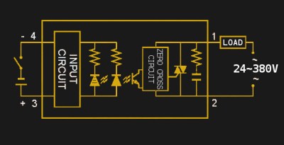
An SSR consists of two or three standard components packed into a module (you can even build one yourself). The first component is an optocoupler which isolates your control circuit from the mains power that you are controlling. Second, a triac, silicon controlled rectifier, or MOSFET that switches the mains power using the output from the optocoupler. Finally, there is usually (but not always) a ‘zero-crossing detection circuit’. This causes the relay to wait until the current it is controlling reaches zero before shutting off. Most SSRs will similarly wait until the mains voltage crosses zero volts before switching on.
If a mechanical relay turns on or off near the peak voltage when supplying AC, there is a sudden drop or rise in current. If you have an inductive load such as an electric motor, this can cause a large transient voltage spike when you turn off the relay, as the magnetic field surrounding the inductive load collapses. Switching a relay during a peak in the mains voltage also causes an electric arc between the relay terminals, wearing them down and contributing to the mechanical failure of the relay.
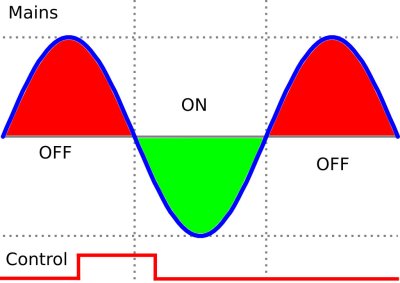
When using an SSR that supports zero-crossing detection, it will maintain its state until the AC output waveform crosses zero on its own. At that point it turns on or off safely.
Dimming with an SSR
One downside to this behavior is that you cannot easily use typical SSRs as pulse-width modulated dimmers, despite their relatively fast switching speeds. Any time you try to control the ‘on’ time of the input signal, the zero-crossing detection will wait until the AC signal crosses zero before switching.
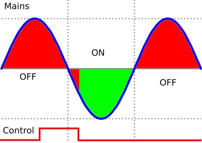
Another type of SSR, called a ‘random turn on’ solid state relay, is used to implement dimming. It works the same way as a normal SSR, except that there is no zero-crossing detection circuit. It simply turns on whenever it receives a signal. This lets you use only part of the AC waveform for certain types of loads such as lamps or heaters. It still waits until the zero-crossing point of the AC signal before turning off though.
SSRs come in DC and AC switching flavors. The type you need to use depends on the type of power you are switching. DC SSRs tend to use power MOSFETs or transistors to handle the switching, rather than triacs or silicon controlled rectifiers.
One quirk with AC SSRs is that measuring the change in resistance across the SSR output when you apply a signal across the input will not provide very useful information. You will continue to see a high resistance across the output. We measured 22 kΩ in this case, which did not let us conclude that the SSR was operating correctly. Bench testing SSRs prior to use is possible with a 9v battery and a lightbulb (PDF warning).
Other Downsides of an SSR
Another potential downside is that SSRs have lower resistance across the output terminals when off compared to mechanical relays, and some leakage current besides. The leakage is typically very small, but if you measure the output of an SSR connected to mains with a multimeter, you will likely register a voltage regardless of whether it is on or not.
Due to the internal construction of SSRs, they are only available in a single-pole, single throw (SPST) configuration. Single pole means that it can only control a single circuit, and single throw means that there are only two positions the switch can be in (one on, and one off state). Mechanical relays do not have this limitation and are available with multiple poles and throws.
SSRs generate more heat than an equivalent mechanical relay. This is because there is a voltage drop across the semiconductors inside the solid state relay, whereas a mechanical relay is just a conductor when active. It’s important to attach a heat sink to SSRs and allow sufficient airflow for any application drawing significant current. For a detailed treatment of SSR safety, check out this document from Omron (PDF warning). It also offers some useful design considerations for different types of load.
When Solid State and Mechanical Team Up
There are some situations where it is beneficial to use both an SSR and a mechanical relay. Lets say that the main shortcoming of SSRs in a design is that they generate more heat than an equivalent relay. Similarly, the main shortcoming of relays in the design is that they are at risk of mechanical failure due to arcing between the contacts every time they turn on.
In this case, it’s possible to combine the two parts in parallel with separate inputs. To activate it, the control system switches on the SSR first. This establishes a current through the load. Next, the control system activates the relay, which does not experience arcing because it’s essentially in parallel to a closed switch. Finally, after a short delay to allow the relay to debounce, the SSR is deactivated. Now all the current flows through the mechanical relay. This allows for an efficient and durable switch, while decreasing the heat sinking requirements for an SSR.
A Quick Test Application – Controlling an SSR with the ESP8266
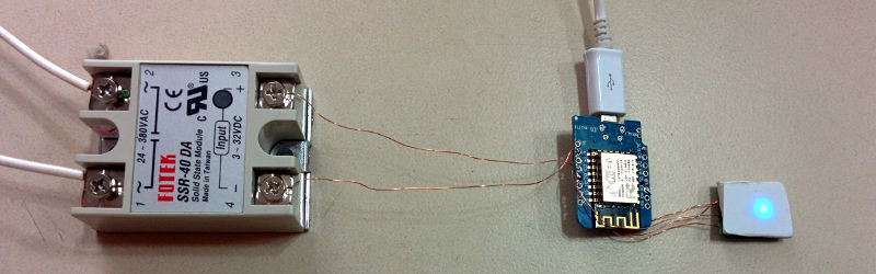
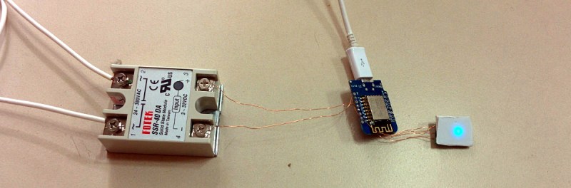
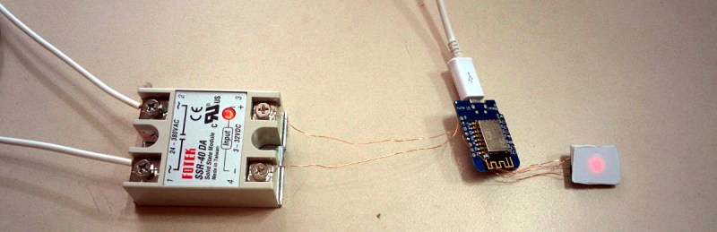
SSRs have a few quirks, but seem like a viable alternative to mechanical relays in today’s fancy Internet of Switches. I’d rather focus on the interesting parts of my automation projects rather than mechanical failure, and frankly all the clicking noises can be a bit much. To get more familiar with SSRs, I built a simple test circuit based on a Fotek SSR-40DA SSR. It is similar in principle to this SSR switched outlet project.
The datasheet says they are rated for up to 40 amperes of current, although this requires a large heat sink, ventilation and genuine parts. In my test I’m using it to control a 47W fan using 220VAC, 50Hz mains power. A heat sink was not judged necessary for this quick test, but I added a one ampere fuse on the mains input to prevent it from being accidentally used for something large. When you have a lot of projects, it’s easy to forget the limitations of each a few months down the line.
I connected the digital output D0 of the ESP8266 directly to the inputs of the SSR. The chip was flashed with NodeMCU and programmed to toggle D0 when a capacitive touch switch was toggled, and I made it change the color of the status LED.
The first thing I noticed was that during the boot up sequence, the pins on the ESP8266 are briefly raised high. This caused the SSR to activate for a short time during startup, which is not acceptable! This can easily be fixed by inverting the signal in hardware with a transistor, then in software.
When the button was pressed, the fan turned on or off accordingly, and so did the indicator light on the SSR. Overall it was very straightforward, although I’ll certainly etch a board properly and add a heat sink before using it at higher currents or extended periods of time.
My mains wiring does not include an electrical ground. This is not due to negligence, but because I’m building this in Vietnam and there is no residential electrical grounding in this country’s infrastructure. If you have grounded residential wiring, please take advantage of that to make your design safer.
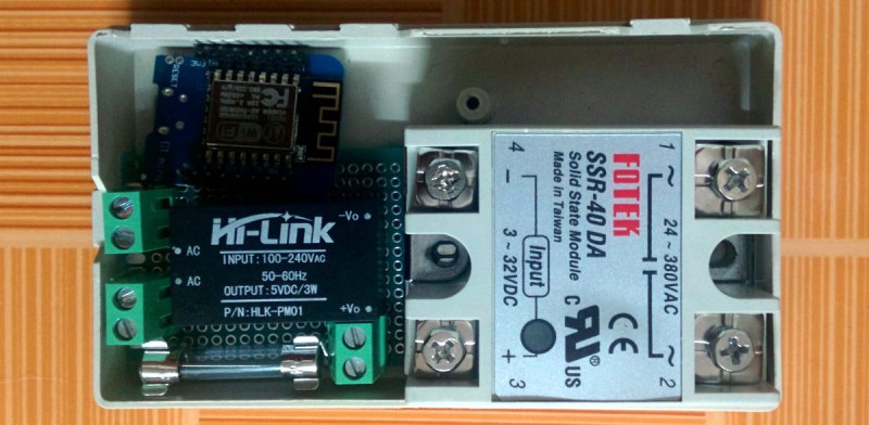
While it’s a trivial test, I learned two practical lessons. First, that the wiring takes up much more space than I thought it would. Second, keeping a safe distance between the wires carrying mains and the signal from the ESP8266 requires some thought in terms of case design (especially for the heat sink on the SSR). It’s not just a matter of stuffing it into a case, and if I’m not going to 3D print a custom one, I’ll certainly err on the side of something larger and with a distinct section for the high and low voltage components. In other words, don’t just do this:
I also learned that illuminated capacitive touch switches fit nicely into light switch enclosures, look pretty sweet, and fit flush with the wall if you trim a few bits of plastic. In later tests, the button is nowhere near the relay. It uses a second ESP8266 that sends a UDP packet to control the relay, and also listens for UDP packets to update the status of the indicator LED if something else turns off the system in question. It worked fine.

Last of all, I’d like to note that counterfeit SSRs are extremely common. Typically, they will fail at currents significantly lower than their rating, even with correct heat sinks. While my SSRs may in fact be genuine, I assume they’re not and will use them well under the rated currents!


I used one of those to build an immersion circulator (Sous Vide controller) via Make Magazine’s article some years ago (and some day I’ll pass along how you can use it to split a quartz composite counter-top while cooking a 48-hour lamb shank!). When my AC failed the other day, the tech pointed out the /next/ item that would fail, and it was a solenoid-based switch, making me wonder why it isn’t solid state. This article was very illuminating on that point.
I thought TRIACs naturally turn themselves off at zero crossing? So the zero crossing circuit is used to turn them on at zero crossing instead of in the middle of the cycle (which would cause a spike to a motor).
The downside to SSR is the 1.7V drop across the TRIAC which turns into heat. At large currents this equals a lot of heat.
On by zero-crossing detection, off by the nature of triac. True!
Hi, i can’t find your esp code. I’m trying to turn a heating element using an ssr and an esp32 via actual button and also via hassio.
Interesting article – I particularly like the chained SSR/Relay gambit, but as a side-issue it’s interesting to note that counterfeits are so prevalent that we now sort of design around them (AVE has a typically profane teardown of an “Omron” solid state timer that’s worth watching – link below). Also, tell us more about how a country has an electrical system without ground connections?
https://www.youtube.com/watch?v=NK1UR7nTqlQ
In everyday life, the lack of ground connections means you avoid touching the metal case of anything that’s plugged in. You lose more desktop computer motherboards than you’d like. You lose a lot of USB hubs too.
When I moved in, I lost power unexpectedly a few days later. I opened up the electrical box, and found that the electrician had installed no circuit breaker and had used a piece of solder as a fuse. It had melted. I bought and installed a safer system myself.
Anyway, a long story short… safe standards can be had here but it’s largely do-it-yourself. This presents both dangers and opportunities. The dangers are obvious, I suppose.
On the other hand, people regularly build their own vehicles from scrap, mad-max style, and sometimes it’s brilliant. Same goes for commercial machinery, houses, etc. Once in a while someone just hacks together something impossibly cool. Other times… not so much.
I have no opinion on whether it’s a good or bad situation, but it’s certainly different.
“… electrician had installed no circuit breaker and had used a piece of solder as a fuse …” – Wow. That is no electrician, and where do you live?
Solder as a fusible wire is totally common in a lot of countrys. In south america, india and africa you can see it everywhere. The “standard” fusebox consists of a knife switch with a ceramic base and screw terminals for the fusible wire. You can buy lengths of the wire (20A, 40A, 60A iirc.) in virtually any hardware store. And, of course, you can ask/hire an electrician to install it… In ancient installations in the USA it’s also still there.
I heard about rednecks “fixing” fuses with a few pieces of thin stranded wire, but solder … is new to me. So, what is the current rating of this solder fusible wire :) ?
Copper pipe inserted in place of glass buss fuses, this handy for melting the wiring harness of (American) automobiles, before European blade type fuses were common here.
U.S. penny in the socket of Edison base, screw in type fuses. Handy for electrical fires in housing. Ironically, it was often, portable, space heaters that were in use and blowing the original fuses, thus the penny insert.
Came here to say this. I’ve had a few of these FOTEK SSRs catch fire before with 10A continuous. I wouldn’t trust them for anything more than 5A continuous at 240V, they’re cheap for a reason.
One thing I noticed with these Fotek SSRs is that they won’t turn on properly if the control voltage is too low. I tried something with 5V (they are rated from 3-32V) and it would sporadically only switch one halfwave of the mains. Maybe theres just bad batches, but unless you can check it with a scope it can be puzzling.
I wasn’t able to to switch on a Fotek SSR with the 3.3V of a RasPi GPIO, I had to push it to 5V with a transistor and a resistor. I don’t know if the limiting factor is the voltage or the amperage, but it now works flawlessly (I use it to turn on and off my 3D printer).
Here is the trick I use: Put the Anode of SSR on +5V and the Cathode to the MCU, so pulling to ground instead of pulling up. Hence you get the 5V diff to properly turn on.
YES! That is the proper way to do it.
Even tie the Cathode high.
MCU sinks more current than it sources.
The Foteks are massively counterfeited, that’s one possible explanation.
If you buy a $4.00 Fotek off Ebay, it’s a counterfeit and you will have problems. They are junk.
If you need something to drive serious amperage only purchase it from reputable sellers like Mouser. Omron is good but pricey.
I just made a battery spot welder using exactly the relay you have pictured. It blew very quickly. As I bought two I stuck the scope on and the “zero crossing” was actually at about 45 degrees. I sent pictures to the manufacturer asking why but heard nothing back. I replaced with a Crydom and that switched at zero but surprised me when I spotted that it takes “up to” 10 ms to switch off once told to, this is specified in the data sheet. “Up to” was really variable so there was no way I could reliably send one peak of AC mains.
Was this 50 hertz setup? It would make sense as one half wave would be 10 mS.
This is because turn off is ALWAYS zero current for a triac or SCR. Non-zero crossing turnoff requires A bit more complicated circuit, and often a bit more dissipation/greater voltage drop. Zero crossing turn on is often sloppy, and it usually doesn’t matter, since a few degrees late is still turn-on at low voltage across the device, and there is only a small power difference in delivered power (a few percent) turning on at 20 degrees rather than zero. 45 degrees is a bit much, though.
It’s not only a matter of power delivered but also harmonics if you choose to control for example a heater. In such case you wish to turn both on and off at zero crossing to avoid higher harmonics.
>The leakage is typically very small
Not really. The Fotek SSR used in this example is 3ma. Some are more. At this level it will certainly cause pain and in certain none common situations could be lethal when the SSR is switched off. Also some low powered devices will be powered or partially powered by this leakage current (I’ve seen it happen), even large inductive loads if they have a digital component to them, the digital component may be on when the SSR is off.
Additionally some of the Chinese knock offs have greater leakage currents.
Always remove power to the SSR before working on any of the devices the SSR powers.
They use Triacs, and Triacs like to fail short, so, keep this in mind when working with them.
And that is why some safety applications only allow “contactors” (mechanical relays). Although it is possible to weld the contacts on some cheap mechanical relays, they generally end up acting like a fuse and splattering the beryllium copper contacts, causing an open circuit condition. And if the coil fails, they just don’t work, instead of failing into an unknown condition.
Ehhhh…
You use contactors when you need to turn on a large inrush current device. You use a separate overcurrent limiting device in-series with the contactor because the contactor is not-so-good at BREAKING large currents. This is used for large motors in machine tools. Contactors ARE NOT to be relied upon to break a shorted / overloaded circuit.
You don’t use TRIACS for large currents because the heatsinking due to VT losses get too expensive or large and you have to worry about self-triggering due to rapid dI/dT or dV/dT.
“When Solid State and Mechanical Team Up
There are some situations where it is beneficial to use both an SSR and a mechanical relay. Lets say that the main shortcoming of SSRs in a design is that they generate more heat than an equivalent relay. Similarly, the main shortcoming of relays in the design is that they are at risk of mechanical failure due to arcing between the contacts every time they turn on.
In this case, it’s possible to combine the two parts in parallel with separate inputs. To activate it, the control system switches on the SSR first. This establishes a current through the load. Next, the control system activates the relay, which does not experience arcing because it’s essentially in parallel to a closed switch. Finally, after a short delay to allow the relay to debounce, the SSR is deactivated. Now all the current flows through the mechanical relay. This allows for an efficient and durable switch, while decreasing the heat sinking requirements for an SSR.”
In this application there is no benefit to using an SSR over a TRIAC, given the cost of an SSR over a TRIAC it woulid be an error to use an SSR. A TRIAC would be used to handle VAC turn on and turn off as it can be rated to handle the necessary current surges in 8.3 ms in low duty cycles. The relay would be switched in after the TRIAC is already on and immediately force off the TRIAC since it would reduce the holding current in the TRIAC to basically zero.
That’s why they use arc extinguishing contactors or breakers in high current applications. They work just fine.
Maybe I’m not thinking of the same thing, but most “overcurrent relays” or “motor protection relays” are relays which trip the motor circuit breaker when they detect an overcurrent condition. So it’s still the circuit breaker that does the actual breaking.
Where I worked we used them to control heaters using a temperature controller. When the SSR failed it left the heater on, the temperature controller was powerless to turn it off. The lesson was to always have another SSR in the circuit to shut things down if the temp exceeded a critical temperature.
O have a box of about 50 or so of these if any one wants some for cheap +shipping let me know, email gravesmarcello@gmail.com
Ebay is also full of counterfeit MECHANICAL relays… Bought a few cheap octal socket “omron” relays a few years ago. I intended to switch the electrical pre-heater in my car engine. Have not dared to use them for that…
“mains wiring does not include an electrical ground. This is not due to negligence, but because I’m building this in Vietnam and there is no residential electrical grounding in this country’s infrastructure”
Not always true, as receptacles for type E, F, and G plugs are increasingly common with new construction. And where only type A and C are available, you should reference your national standards for product safety, such as QCVN 22:2010/BTTTT. There are specific Class II construction requirements where equipment has no ground bond.
As Vietnam’s grid becomes more interconnected with Cambodia and China, surge problems will become more common. Where no local reliable ground bonding is available, surge protection becomes more difficult and expensive, because a direct earthing of neutral inherently delimits over-voltage conditions.
Some history. Vietnam, having been ravaged by multi-generational wars, directed most Cu to military use (and used Al for electrical distribution), so the neutral wire is unearthed to save on raw materials. Suspect that a central design reason is because unearthed neutral, while less safe, is less apt to take down the ‘local’ grid during fault conditions.
I did an installation in the Philippines a few years ago. There a “one phase supply” was just that. One wire from the grid, supply your own return job. Mind you when the whole are is underwater by 6 ft when the tide comes in I don’t think earth return is much of a problem.
You can of course simply hammer a long metal rod into the ground and wire that up into the home to get a ground. The depth and length of said rod depends on the dryness of the soil though, but that’s obvious.
Ah, thanks! I’ve lived mostly in older buildings these last years and this makes perfect sense. I toured some recent construction not long ago, and they did in fact include a 3-pronged, properly grounded plug as you say.
I don’t think they had smoke detectors yet, but I can just bring my own, and those are slowly becoming more common too. I find it exciting to see all these things develop!
I am not an EE,
and I do not know the specs.
But I do know a lot of SSD an be found in auto junk yards.
The most common use is the transmission “lock up” into overdrive.
It is often placed on the inner fender well and super easy to get to.
If you do not want to get yours shows dirty, the local auto parts store will have them.
“transmission “lock up” into overdrive.”
I take it you are also not a mechanic.
I think the control waveform in your second example picture is wrong.
(Also you’ve inverted the usual electrical industry convention of red=on, green=off, that’s no big deal, but I would just shade the ON part, easier for the colourblind people)
Agreed, should turn on in line with the rising edge of “control” and off with the zero crossing at the end of the negative portion of the cycle.
I hadn’t considered colorblindness. Thanks for bringing it up, I’ll try to keep it in consideration in future diagrams.
That’s a NICE writeup! Hand a newbie this article and parts and there will be success! Ask for a promotion.
bigclive did a nice teardown of an imported SSR. I think it was a 25A unit and the triac in it was rated for under that. 15 or 20A I think. Oh, those Chinese!
It was 25 A until he opened the case that was heatsinked to the SSR :))) After opening, only 15 A :)
But the triac would also be fake, and so its ratings might not be correctly marked and the Chinese will argue it’s really 25A.
And with fake parts that’s even possible, I’ve seen videos where a fake device actually had better specs than they marked on it.
The inner workings of a FOTEK SSR.
http://www.kegkits.com/SSRs.htm
I had a ssr controlling a hot water geyser, it was properly heat sinked, never got above 40C and was housed in the mains switchboard without a secondary enclosure. Early one morning, as the ssr turned on, it started a fire and burned to a crisp. The smoke of burning plastic was overwhelming and it covered the inside of the switchboard with a thick layer of sticky soot. The lesson learnt: always mount ssr’s in their own metallic enclosure. The few bucks you save are not worth it if it burns your house down.
I a hobbyist, not an engineer. Why do you need both a triac and an optocoupler? doesn’t the optocoupler already isolate the control circuit and switch the controlled circuit? Is it a load thing? That is, the optocoupler cannot handle a real load, so we shift that duty to the triac? Forgive me if this is obvious, but from a casual’s perspective it seems redundant.
Yes your guess is right.
Plus that zero crossing thing of course, you need it for that too.
I wouldn’t trust those FOTEK SSRs for anything more than 5A continuous. I’ve had a few catch fire trying to run 2400W heating coils through them at 240v.
Hmmmm, well there is often quite a surge also when motor loads for example are turned OFF, so that needs to be supressed. Maybe just a snubber circuit on the mechanical relays ?
At first I think about adding another mechanical relay just past the SSR (would still suffer momentary arcing though without a snubber circuit), that feature totally isolates the load and load wiring from the SSR when the SSR is not energized, no SSR leakage can slip past the SSR – – the other relay is still there in parallel to run the load after the SSR system is de-energized.
But the more I think about it the more I like getting rid of the SSR and just using snubber circuits on mechanical relays, an electrical engineer once explained to me that zero crossing SSR’s would not always solve this surge problem for me.
And plus it seems you still need to design and engineer for the surge that occurs when the load is turned off which will likely arc the contacts of the mechanical relay which is powering the load when the control signal is removed and the contacts open. Even if I’m wrong about arc when mechanical contacts open, there is still a rather large harmonic / spike along the wiring from the mechanical relay to the load to suppress when those contacts open, in my case could be up to 300 feet to a submersible pump running at 20 amps, 240 volts out in a lake with an industrial 20 ma GFCI subject to nuisance tripping . . . .
According to the UL notification:
http://www.ul.com/newsroom/publicnotices/ul-warns-of-solid-state-relay-with-counterfeit-ul-recognition-mark-release-13pn-52/
I reckon the SSR in the picture is one of the fakes. Genuine Fotek parts have a chamfer in the bottom right corner of the front panel recess. The fakes are square in all four corners. I then noticed the cheap ‘Fotek’ SSRs on eBay appear to have a chamfered sticker on the front, but the plastic is still square (presumably they didn’t want to pay for retooling the injection mould for the case, but paying someone to cut the corner off the sticker was a good wheeze)
I’m in the market for some SSRs (but looking to buy some Crydom ones instead) but I just couldn’t buy anything from Fotek for this reason. I’m seriously considering just going old-school and building what I need from opto-couplers and discrete triacs instead.
Yeah, I noticed that too. Even on the safer etched PCB I’ve rebuilt for this project, I won’t be passing more than 5 Amperes through them, with a heatsink. The cheapest, lowest amperage locally available SSRs are rated at 2 Amperes, and these big “Fotek”s are “rated” for 40 so probably it will be fine.
If not, you’ll all get a very entertaining follow up article on SSR failure states when I do stress testing.
“The first thing I noticed was that during the boot up sequence, the pins on the ESP8266 are briefly raised high”
D0 seems to be actively pulled high during reset and in deep sleep.
Use D1(gpio4), D2(gpio5) or the rx pin(d9/gpio3). These pins are always quite.
Can you please post a link to those nice capacitive touch switches!?
Thanks
Sorry I caught your question so late, but here you go:
http://hshop.vn/products/camung-1-chamdien-dung
It’s in Vietnamese (I try to source locally) but you should be able to find it elsewhere with the part number in the image.