Face it — you want a reflow oven. Even the steadiest hands and best eyes only yield “meh” results with a manual iron on SMD boards, and forget about being able to scale up to production. But what controller should you use when you build your oven, and what features should it support? Don’t worry — you can have all the features with this open source reflow oven controller.
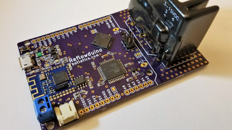
Dubbed the Reflowduino for obvious reasons, [Timothy Woo]’s Hackaday Prize entry has everything you need in a reflow oven controller, and a few things you never knew you needed. Based on an ATMega32, the Reflowduino takes care of the usual tasks of a reflow controller, namely running the PID loop needed to accurately control the oven’s temperature and control the heating profile. We thought the inclusion of a Bluetooth module was a bit strange at first, but [Timothy] explains that it’s a whole lot easier to implement the controller’s UI in software than in hardware, and it saves a bunch of IO on the microcontroller. The support for a LiPo battery is somewhat baffling, as the cases where this would be useful seem limited since the toaster oven or hot plate would still need a mains supply. But the sounder that plays Star Wars tunes when a cycle is over? That’s just for fun.
Hats off to [Timothy] for a first-rate build and excellent documentation, which delves into PID theory as well as giving detailed instructions for every step of the build. Want to try lower-end reflow? Pull out a halogen work light, or perhaps fire up that propane torch.


I should get this or something like it one day. I regularly see working toaster oven for under $5 at Goodwill. A thorough cleaning and it should be good for SMD soldering.
Nothing a little Lye won’t clean.
I see them too with the new thoughts based on the soldering skills I haven’t acquired just yet. I was thinking some insulation work might not hurt also. Seems I’ve read about reflectors too and additional heating elements based on design.
Aquire those manual soldering skills first and you will always have them. Then build your reflow oven. Build the oven first and you might not be motivated to go any farther.
@Bob: I totally agree! :)
Will do. Thanks for the affirmation. Seems my progression is wafer board to dead bug to non-SMD PCB confidence (amazing how the Kester 186 flux significantly improved performance), no burning out electrolytic capacitors so higher temp faster with flux and damp towel to cool immediately after looks like the plan, then larger surface higher temperature confidence which doesn’t look so challenging.
Then SMD’s working my way down to smaller sizes where I am finding a microscope or at least the cheap USB Microscope I picket up with an adjustable arm bench mount CFL ring light I replaced with a White LED Ring light that I can adjust and UV Ring Light that I can adjust aids in being more accurate. With the smaller items the braid wicks post soldering seems to be a way too the clean up solder shorts if was messy. I ordered a pair of spring loaded reverse stainless steel tweezers also to heat transfer and make the holding of the small components easier. I’m observing that certain size SMD components and smaller, the reflow ovens are the way as well as for fabrication of more volume of boards.
I must be trying the wrong toaster ovens – I’ve done some tests on a few just sticking a thermometer probe in and turning the unit on full and watching the temperature rise and they take a few minutes to slowly climb to temp which seems to long for the required temperature profile :(
Use the “oven” part of toaster-oven and preheat to 150 F or so. I have an old one and it works fine. I ramp it by hand with the temperature knob. I recently saw a used very large one that had a rotisserie, which means I can put a fan inside very easily.
Yeah you need to select the toaster carefully. You want one with quartz heating elements. You’ll also need to insulate it with high temp insulation. The toaster I used was a $20 rival unit from Walmart. I built one following this dude’s guide on youtube ( https://www.youtube.com/watch?v=rZyP5G4Wfm0 ) exactly and I’ve made dozens of complex smd pcbs with it getting near perfect results.
+1 quartz and insulation.
… and external fan motor with shaft to internal fan blades.
Even better.
I use an electric skillet, an earlier model of this one which was on sale at Walmart for $9.XX when they came out with a new model with a ceramic non-stick coating instead of Teflon. The glass lid acts as an IR reflector and allows one to see the process:
https://www.amazon.com/Oster-CKSTSKFM12-ECO-DuraCeramic-Electric-Skillet/dp/B00ITPJ1DA
I came up with 30 sec to 1 minute timed on/off cycles measuring temperature with a non-contact IR thermometer to approximate well enough the desired temperature curve and just manually do the on/off cycles using a stopwatch.
I use mine by just preheating the oven to suitable temperature (250 C seems to work for me), putting the PCB in for a minute, and then taking it out. But it does have a fan so that speeds up the heat transfer quite a bit.
Two years ago, I bought what seems to be the “wrong” type of oven for reflow: a 23lt resistive heating 1500W oven (i.e. not infrared). I modded it by adding mineral wool for additional isolation.
I built a reflow controller based on this great resource, removing anything I didn’t need such as bluetooth:
http://andybrown.me.uk/2015/07/12/awreflow2/
Even with some tweaking of the PID values, the temperature in the oven does not follow the ideal profile. It lags by 10 seconds when rapid changes in temperature should occur and it briefly overshoots by 5 to 10 degrees in some cases.
But it works. I’ve been using it with lead-free solder and I have never burned or messed up a board in 2 years. My conclusion is that for small volumes, you don’t need to follow reflow profiles religiously. Even manually operating the oven without a controller will likely work in most cases if you have a bit of practice.
Thanks for th tips.
All is not lost then – I’ve got some solder past and some bits and pieces. I should just give it a shot one afternoon.
Without really reading the linked post in detail it seems to me that they use continuous PID control instead of time-proportioning control. Because the oven has thermal mass, this means that there will be significant lag and continuous PID control will result in lots of little overshoots where each little section is like the a set point temperature PID response curve.
I bought a couple of BMP 180 chips a couple years ago. I didn’t know that they were BGA.
Could a toaster oven be used to solder those to a PCB?
(I have seen where some brave person soldered directly to the balls on a small chip like that, I’m not sure that would work for me.)
Does OSHPark “do” small BGA footprints?
Yes, I’ve heard of people soldering small BGA RAM modules or voltage regulators with a toaster oven, but it’ll be hell to verify all the connections. Also, OSHPark only does up to 4-layer boards, which should be fine for something small like a 4×4-ball chip, but for larger chips you’d probably need 6-8.
It’s probably best to avoid BGA if you don’t have a pick-and-place, unless you really can’t avoid it. Ovens make QFN chips way easier, though.
Thanks!
Oh, I found a BMP180 BGA board on OSHPark’s “Shared” pages…
https://644db4de3505c40a0444-327723bce298e3ff5813fb42baeefbaa.ssl.cf1.rackcdn.com/49c87500fa88a855f6ca49368290736c.png
It is a WeatherShield for a Moteino v3
https://oshpark.com/shared_projects/sXFRCOgp
Don’t bga balls age quickly (to the point of being impossible to solder) — unless kept in inert storage?
The BMP180 is well within OSH Park’s capabilities, and can also be soldered with a hot air rework station (which I would say is a higher priority than having an oven). Compared to most BGA packages, those LGAs (they don’t have solder balls, just gold-plated lands on the bottom of the tiny PCB package) have quite large features. Inspecting the joints pretty much requires a microscope and a clear view from around the sides of the package, though, so it’s a matter of “cook and pray” if you don’t have that.
I’ve done similar LGA parts without even the convenience of solder paste, much less an oven — just dome up some solder on the pads with an iron, clean and apply fresh flux (I’m partial to ChipQuik SMD291, which is a no-clean flux that can be had in small squeeze tubes for pretty cheap), preheat the board with hot air, drop the part on, heat to reflow, and poke the part into place if necessary (e.g. if your hot air gun has blown it a bit off the pads). You have to avoid the temptation to go nuts with the flux, since atmospheric sensors don’t take well to cleaning with solvents.
Great effort, checkout this link for more toaster oven reflow ideas: http://reprap.org/wiki/Toaster_Oven_Reflow_Technique
I’ve been using the thermistor version for a long time with no problems.
Even with opto-isolation, having mains voltage and low voltage on the same physical PCB I’d be inclined to have isolation slots in the board. I feel they would provide better failure modes for many unplanned events.
There are design rules to be followed when having mains voltages on circuit boards. I really do hope that he respected all these rules in his design, Slots in the board are used to allow you to get from the higher minimal creepage to the lower clearance rule.
If you need to know more, IPC-2221 (generic standard for guidance on PCB design clearance and creepage) or IEC-60950-1 (2nd Ed.) would be the goto rules.
If the design is “Arrow approved” i do hope they actually double checked his design for these safety aspects, especially if he wants to sell this as a product.
Hey guys, thanks for all the comments! Yes, IPC-2221A Table 6.1 says that the spacing between uncoated external conductors for 301-500V should be at least 2.5mm, and currently the spacing of the pads is >7.6mm. For the internal planes (internal conductors) the IPC spacing should be at least 0.25mm but they’re 1.27mm.
However, I’m always open to suggestions and comments to make Reflowduino better!
~Tim
Update: Hey guys, I just updated the Reflowduino PCB design to include a cutout between the relay output pads. Thanks for the suggestion and I hope you feel better now! :)
I like the project (anything that teaches PID principles is awesome) but still argue that reflow controllers are unnecessary for hobby-scale work. I picked up a decent quartz-element convection toaster oven and like a previous poster in this thread, run it through the preheat cycle for ~4 minutes. I’ve done many hundreds of boards this way with fine features (0.5mm QFN, LGA, etc) without any trouble.
Yup that definitely works too, whatever toasts your boat! Gosh, I used to use hand-adjustments on a cheap hot plate and it worked, but the results are much better with a toaster oven. I mainly wanted to create something cool that I could share with everyone as an open-source project and a PCB that could also be adapted to general use as well (hence the Reflowduino Basic). Even if you don’t use it to control your oven, at least it’s an Arduino Leonardo with LiPo battery support and BLE, and you can simply control your oven via a solid-state relay only when you want to. However, for those who want to build more complex reflow setups (like with convection ovens, etc), Reflowduino could be interesting for them!
Hey zak – I missed your comment and posted my own that says pretty much the same thing. I completely agree with you. I’ve never understood the obsession with trying to follow the recommended profiles. The good results achieved when just using a constant temperature seem to speak for themselves.
I just use a convection toaster oven. I turn it up to about 200C for leaded solder and put the parts in when it’s hot. I leave them in for about 3 minutes. I’ve never had any issues even though I’m not following the recommended profile.
The recommended solder profiles are to provide good solder reflow without shocking the parts thermally. All plastic devices absorb moisture which will literally boil during reflow soldering and can cause damage to the part. The damage may not cause failure immediately but increases the likelihood of failure later. So adherence to recommended profile is not strictly required for hobby applications but if you are producing boards for sale you should follow the solder reflow profile as well as observing the manufacturer’s recommendations for plastic device internal moisture levels. I am a retired semiconductor reliability engineer who qualified devices to reflow profiles and have worked with customers and vendors on reflow issues.
Observation: Follow recommended profile and you’ll usually get good results. Ignore it, and your mileage may very! since it’s pretty easy to follow (reasonably) the profile, why not?
That said, I’ve had good luck with this: https://hackaday.com/2015/02/02/reflow-chateau/
I’ve also done a lot of work with this: https://hackaday.com/2009/01/31/surface-mount-soldering-in-depth/
with more details here: https://www.instructables.com/id/Closing-the-Loop-on-Surface-Mount-Soldering/