With 3D printers now dropping to record low prices, more and more people are getting on the additive manufacturing bandwagon. As a long time believer in consumer-level desktop 3D printing, this is a very exciting time for me; the creativity coming out of places like Thingiverse or the 3D printing communities on Reddit is absolutely incredible. But the realist in me knows that despite what slick promotional material from the manufacturers may lead you to believe, these aren’t Star Trek-level replicators. What comes out of these machines is often riddled with imperfections (from small to soul crushing), and can require considerable cleanup work before they start to look like finished pieces.
If all you hope to get out of your 3D printer are some decent toy boats and some low-poly Pokemon, then have no fear. Even the most finicky of cheap printers can pump those out all day. But if you’re looking to build display pieces, cosplay props, or even prototypes that are worth showing to investors, you’ve got some work cut out for you.
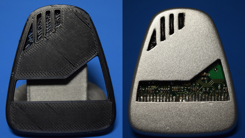
With time, patience, and a few commercial products, you can accomplish the ultimate goal: turning a 3D printed object into something that doesn’t look like it was 3D printed. For the purposes of this demonstration I’ll be creating a replica of the mobile emitter used by the “Emergency Medical Hologram” in Star Trek: Voyager. I can neither confirm nor deny I selected this example due to the fact that I’m currently re-watching Voyager on Netflix. Let’s make it look good.
Choosing Layer Height
Before you get out your sandpaper or paints, before the print has even started, you need to make a decision. As anyone who’s used a 3D printer can tell you, layer height is the biggest factor in overall print time. Thicker layers are faster, but result in loss of surface detail. You need to decide before the print even begins if the higher resolution settings are worth the additional time, and the only way to do that is with a clear idea of how the printer’s resolution will effect your final product.
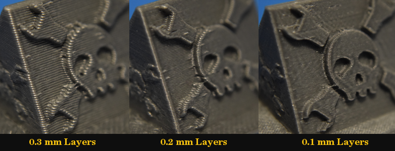
The following image illustrates the effect the three most common layer heights (0.3 mm, 0.2 mm, and 0.1 mm) have on final print quality. For reference, the skull in the Hackaday logo is a bit bigger than Lincoln’s head on a US penny.
Looking at this image you may assume that you should just leave your slicer set to 0.1 mm, and deal with the increased print times. But I intentionally created an example that would really accentuate the differences between the layer heights. You won’t always be dealing with surface details this small, and there’s no sense printing at 0.1 mm layers unless you’ve got a good reason to do so.
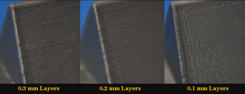
To show you why layer height may or may not be important for your specific model, let’s flip these demos around and look at the backs:
The layers are still more visible on the 0.3 mm print, but overall the difference between the three is not nearly as pronounced. With no detail to show the layer heights, a flat surface ends up being…well, flat. Moral of the story: don’t bother using lower layer heights if your model doesn’t have surface detail worth putting the resolution into.
If you intend on finishing a print with the following methods, I would personally stick to 0.2 mm, and if it’s a large print with a relatively simple shape, kick it up to 0.3 mm to save time. Either way, the finished product is going to be smoothed out, so there’s no reason to worry about visible layer lines when it first comes off the printer.
Step 0: Printing
So now that you hopefully figured out what layer height suits your model, you need to actually print it out. This first step sounds easy enough, but remember that you want to start with a well calibrated 3D printer if you’re trying to turn out high quality pieces. Make sure your bed is level, and check your extrusion multiplier to make sure you aren’t over- or under-extruding. Printing some benchmarks are very helpful to get your printer dialed in, and you should really take the time to do it right as it’s only going to save you aggravation in the long run.
Control Example
So you may be wondering why you can’t print your piece at the lowest layer height your machine supports, wait it out, and then just paint it as it comes off the bed. Well, you can, but the results aren’t going to be much different from having just printed it in a colored filament. But you asked for it, so let’s take a look at how that comes out and call it our “Control” for this demonstration:
If this was a few hours before you had to hit a Halloween party, this will probably look good enough at arms length that you could get away with it. But on the shelf next to my autographed picture of James “Scotty” Doohan? No sir, it just won’t do.
Step 1: Sanding
Do you like sanding? No, of course you don’t. Nobody does. But you’re going to be doing a fair bit of it, so you might as well get used to the idea. This early I use an 80 grit dry sanding block, and really attack it. I find printing in black helps during this phase, as the black filament will turn white/gray as it gets sanded down and it makes it easier to see what you’re doing. Once you’ve knocked off all the shine and the piece starts looking dull, you’re on the right track.
Step 2: Epoxy Coating
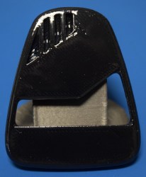 I’m a big fan of XTC-3D, a two-part epoxy product specifically designed for smoothing and sealing 3D prints. It’s fairly cheap, goes a long way, and I think the results speak for themselves. I don’t want to turn this into a guide for using XTC-3D (check out YouTube for some official howtos from the manufacturer), but generally speaking: mix up about 7 ml at a time and brush it on once it starts to get a little tacky with a disposable brush. The idea is to put it on when it’s still liquid enough to find its own level, which allows it to fill in the layer lines and leave you with a hard and smooth surface.
There’s definitely a learning curve with XTC-3D. It’s easy to put on too much and wipe away surface detail, but too thin and the coating doesn’t have an effect. I suggest trying on some scrap prints beforehand to get a feel for how it should flow. Cure time on the XTC-3D is about 24 hours, so block out enough time for this step before trying to move on.
Step 3: Sand and Fill
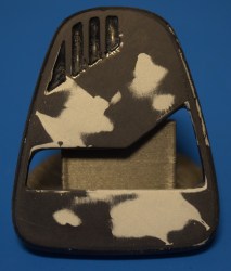 At this point I use a 220 grit wet paper to take the shine off the cured XTC-3D and get it ready for the primer. Like when you sanded the raw printed part, you want to keep going until the whole surface has a dull look. Anything still shiny after sanding is going to be a low spot, and needs to get filled in. My filler of choice is Tamiya “Basic Type” putty. This is basically Bondo for plastic model kits, and dries extremely fast. You’ve got maybe 30 seconds working time from when you squeeze this out of the tube to when it hardens, so don’t try to do too much at once.
After you’ve filled the low spots with the putty, you want to go over it again with the 220 wet paper. The goal here is to fill in the dips and nicks with the putty and blend it in on the surface. The edges of the putty should generally have a “cloudy” look, and you should definitely not be able to feel it if you run your finger over the surface.
Step 4: Primer
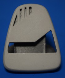 Once you’re happy with how smooth the piece is, it’s time to prime it. I use Rust-Oleum Filler Primer because it’s cheap and easy to find basically anywhere. As the name suggests this primer is fairly thick and will further fill in any imperfections that you missed in the previous steps. I like to do three coats of primer, followed by wet sanding at 400 grit. At this point, your piece should basically feel like glass.
If you’re planning a paint job that’s really going to show surface imperfections, you can do one final sanding pass with 800 grit wet paper to knock off any runs in the primer or bits of dust that might have fallen on the piece while it was drying.
Step 5: Paint and Clear Coat
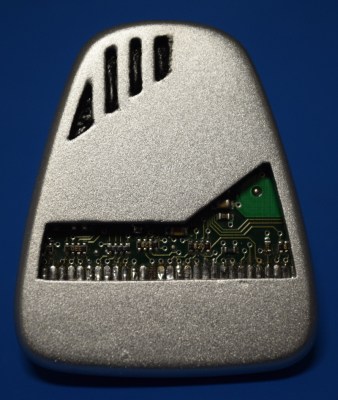 All that’s left now is to do your final painting. As it turns out, I am pretty terrible with a brush or indeed anything remotely similar to art, so I only use spray cans from the hardware store. For this piece I used a basic silver metallic spray paint, followed by a clear matte to take down the shine and give a bit more realistic surface texture.
Final Thoughts
While this method may seem like a lot of effort, I think it illustrates a fact which more people are coming to realize: 3D printers don’t work miracles, they are a tool like any other. In the same way that you can’t just throw a tree at a table saw and expect a dining room table to come out the other end, it’s important to understand that 3D printing should be considered just one step in the overall process of taking an idea from digital to physical. A big step, granted, but not necessarily the final one.
Some may look at this example and claim I “cheated”, as the majority of the surface of the piece was smashed down onto the bed and therefore relatively flat to begin with. That may be true, but if you follow the steps and look for the visual clues demonstrated in the images, this method will work just as well on the sides of printed objects as it will on the top and bottom. This is the same procedure I used to get the smooth metallic finish on my ThinkGeek-inspired Star Trek phone dock last year, which had exceptionally little surface area on the print bed.
Of course, this isn’t the only way to finish 3D printed parts. We’d love to hear how you’re finishing your prints and getting that not-printed look on your projects.





“What comes out of these machines is often riddled with imperfections (from small to soul crushing), and can require considerable cleanup work before they start to look like finished pieces.”
I imagine with most entries being bottom-of-the-barrel printers the limitations are greater.
I’m not sure that’s entirely right. I have a bottom-of-the-barrel printer (kit!) that is probably something like 90% of a top-shelf printer. The differences between the most expensive and the least expensive are not all that great.
Most of the gains at the high end these days are in fool-proofing the printer. If you know what you’re doing, a super-cheapy will perform nearly as well. IMO/IME.
Absolutely, the lines have definitely blurred between the different “classes” of 3D printers, as long as you’re willing to put in time calibrating it. You can get the same quality prints from an i3 clone as you can an official Prusa for 2 – 3 times the price, but the Prusa is going to do it out of the box all the time every time, and the other is going to need some babysitting and probably some modifications.
But in general, the next generation is all about reliability and fool-proofing the process. To use the Prusa as an example again, all the major changes for the new version have been in the areas of sensors, reliability, and error-correction. Actual print quality is going to be the same as the MK2.
Realistically, we’ve more or less hit the limit of what you can do with FDM machines (beyond going down to smaller nozzle sizes like .2 mm, but print times go up dramatically). To get “better” prints you really need to move on to other technologies, but they have their own issues so…
.2mm doesn’t increase print times nearly as much as you’d think. Something like 10-15% over a .4mm nozzle.
Well, I think he is asuming same weight (somewhat transferable to strength of the part). If you are doing twice the amount of walls it will take close to 100% more time to print with a .2 then a .4 (of course assuming the print thicknes is also identical to the nozle size)
i agree. my printer is a cheap kossel kit that i have put a lot of work into. i definitely improved it a bunch to go from not really meeting my standards to mostly meeting my standards. on the other hand, my standards don’t really go for presentation pieces, so it still has a ton of flaws that i know about and compensate for.
what i’m trying to say is that my printer is not very good and i think the reason is that i don’t mind – the problem is in the guy who maintains the printer.
nice article! More like this.
+1
*1 for an honest appraisal and useful technique.
The references are not quite up to par though
” a bit bigger than Lincoln’s head on a US penny.”
Guess what countries don’t have US pennies? I give you a hint: it starts with ‘all of t…’.
Well, perhaps we could say about 3/4 of an inch…. oh hang on, that’s just the US now anyway….
Give me your address, and I’ll send you one.
Some of you people are really ridiculous with this stuff. These are American authors on an American website, get over it. It took you longer to write this comment then Google a comparison pic between a penny and whatever your local currency is.
It’s a website that goes out of its way to get an international public to the site. From my own point of view, I’ve been invited to European tours, European conferences, European ‘Unconferences’, visits to hackerspaces and so on.
With that in mind, I would be very much surprised if more than 25% of the Hackaday readers are from the US. So why keep annoying the majority of your readers with those US-only references and US customary units that pop up in a lot of articles?
25%?? You can’t possibly be serious with that figure. Where are you getting this information?
I’ll grant you it might be 50/50 or so between international and US traffic, but there’s no way the US isn’t FAR and away the single biggest contributor to views.
‘murricar!!!11
I bet many readers, if not most readers, are from overseas. The editors are elsewhere in the world as well.
Although steps like this are needed to get a nice looking part. Sometimes depending on the part use this isnt needed. if im printing an enclosure for a project they way it looks off the print bed is fine to me.
Probably 80 – 90 % of my prints are used right as they are off the bed. I tend to print practical objects and parts, so dimensional accuracy is all I’m worried about; the looks don’t even factor into it.
But if I want to do something for display, or to show off an idea, sometimes that traditional “printed” look doesn’t quite cut it.
Great piece, I’ve been waiting for something like this! Very informative.
A couple of things you might want to try. First, Mirka abralon pads. They are advertised for bowling balls, but do a superb job of high quality finish sanding/buffing on wood and plastic. They go up to 4000 grit. Second, if you’re doing enough stuff, an airbrush is going to give you better control and a more even finish than a rattlecan.
“In the same way that you can’t just throw a tree at a table saw and expect a dining room table to come out the other end.”
Best comparison ever written for 3D printers.
*Starts thinking of ways to design a fully automated tree to table production machine*
Sees your patent, starts thinking of a way to automatically grow tables.
Umm… is it weird that I immediately recognized it as the Doctor’s mobile emitter before reading anything. ;P
Not at all. At least… well maybe I’m weird too.
This would be one prop I’d make too.
Am I alone in looking at the 0.1mm sample and thinking that the printer needs tuning or that the slicer settings are wrong? That vibration wobble is not good.
Yep, now I see it too. Though it is a very small error, if it would be visible in the 0.3mm then you need to get out the tools and fix it, this little wobble is acceptable for me. Especially considering that the sanding filling and painting etc is going to mask it anyway.
I’m not sure that you can’t see it at 0.3mm, it’s just that the effect is different. It appears to be taking the right angle corner too quickly, and is overshooting. The wobble on 0.1mm is ringing as the head settles back to it’s programmed path. At 0.3mm it still bulges out at the corner. What I think it needs is an adjustment to the slicer or firmware settings so that it slows enough for the corner that this effect is removed.
It isn’t just horizontal ringing that causes that. Non-repeating bulges or recesses can be caused by a discontinuity between the horizontal motion of the nozzle and the extrusion of filament from the nozzle. The outer shell (and the inner shell) may unintentionally end up thicker in certain places than others.
Each line the hot end follows relative to the bed isn’t at constant speed. It “jerks” to its starting velocity (speed and direction), accelerates (possibly to its maximum speed), possibly plateaus at its maximum speed, decelerates back to the “jerk” speed, and then jerks (changing direction) to the starting velocity of the next line. In Marlin, by default, the extruder motor follows an identical, scaled acceleration profile, based on the not-quite-correct assumption that every linear micrometer of filament driven by the filament drive exactly corresponds to that volume of filament passing through the orifice of the nozzle at the same instant.
The falsehood of that assumption is why ooze/stringing happens, and why retraction is necessary, especially with Bowden cables, and especially with flexible materials. The filament between the filament drive and the nozzle is somewhat compressible under pressure, and it’s pressure that pushes it out the nozzle.
There’s a feature in Marlin that can be enabled and compiled in called Linear Advance (look in configuration_adv.h), which makes the extruder motor follow a different (configurable with M900) movement profile intended to achieve a better correlation between x/y movement and actual extrusion of plastic from the nozzle during acceleration and deceleration. Another implementation of this compensation also exists in the Sailfish firmware called JKN Advance.
Me being a person who has worked with his hands forever, and never being satisfied but rather nitpicky and critical all that time, I feel you on this point. I’m often amazed at what some folks exclaim to be “great quality” when it obviously is just better than it was (hopefully) but certainly not comparable to actual good craftsmanship. I see it on home improvement shows all the time too when the host will cobble something simple together with drywall screws, not even use glue, slather on some paint, beat it with a chain to give it “aged character” and everyone acts like it’s a design masterpiece.
I do like the end result of the authors project tons better than the off-the-bed print, but it’s certainly not crisp (holy cow, those corners!) and not a fine piece of jewelry. It probably only needs one or at most two further steps and an hour or so time to bring it up to display quality.
So close…
Still, the article is definitely informative and points relative 3D printer newcomers a good direction. Bravo.
Some people obsess over making their TV and movie prop replicas *better* than the originals, especially for stuff from the 90’s and earlier. When I first got on the net back in 1996, some of the first stuff I looked up was Battlestar Galactica (the original of course) and Buck Rogers in the 25th Century.
I was shocked, *shocked* I say, at how crude and crappily made most of the props were. They looked so neat and nifty on TV! But seeing “high res” (like 640×480) closeup pics it was obvious that if someone spent an hour making some of them they were wasting time.
So of course there are the sort of fans who are just as nitpicky precise and fussing over their replicas, to make them look as close to the crude originals as possible. They just have to copy the precise degree of crookedness in the fake buttons, and the details in the painted over glue ooze out that didn’t get cleaned up because the prop had to be on set just as soon as it could be handled by the actors.
Part of my need for high quality and pursuit of perfection come from when i was still an art major. I will never forget my design professors first assignment and his response to the entire class on turn in. The project wasn’t super complex but the presentation requirements where. It also stood with a stipulation that if the quality and project wasn’t up to his standard you got an F for the entire class. On turn in day 60% of the massively overfilled class had dropped. A that point he explained if your not going to do or atleast try to present professional quality work than the class wasn’t for you.
having since worked as a finish carpenter, only compounds on that lesson. while bosses often complained about attention to detail on the basis of time costs. I never had an unhappy customer when it came to quality concerns. Plus i was eventually promoted on the fact that i could balance quality and time or deal with a very demanding project/customer with great results.
Yes, I blew my design course way back, I couldn’t do the quality/time balance, it’d take me fkn hours to produce one preliminary idea drawing, I had the ideas, just could not get them down fast enough in acceptable, presentable quality. It leeched every spare moment when I had several other courses, so I stopped turning up.
It’s a lot of processing for just a toilet fragrance diffuser…
One of the processes i use regularly these days is to electroform the printed part in Copper and then nickel, its not a quick process but the finish is really robust and hard wearing.
https://scontent.fakl2-1.fna.fbcdn.net/v/t1.0-9/23659506_1414633081999557_7693860433086639986_n.jpg?oh=1e50ad95bca7805155277b00d9cac07e&oe=5AAE236D
\
It’s also conveniently guaranteed to disintegrate in a few years due to thermal stresses and decomposition of the plastic. Lovely! Our great grandchildren will treasure this absolute trash.
Lol, I have been electroforming things for well over 10 years, 5 years ago I did my first ever 3D print and still have it. no cracks, no chips and other than the occasional polish its stood up prety well. Same as many of the skulls I have done and other organic things like roses. Some of the roses are over 10 years old.
Stress in the plastic after printing is prety easy to relieve prior to the plating, then taking in to consideration things like current density, the solution and the anodes and a few other factors you can reduce the stress a huge amount.
But like every forum there has to be the occasional troll who keen to shoot down the work of another regardless of the fast that that person has been doing his craft for many years.
Disappointed to see your link was just to a pic, and the name-link to facebook. Got any useful links for electroforming, plastic stress reduction etc? This is something I want to try with my 3d printer…
I have not had the time to really write anything up of late other than what I have posted in a few forums regarding the process. but may do so and post it in HA.IO at some stage in the near future.
Look forwards to it!
Very very useful topic. Lot’s of information here.
Sometimes I use Plasti Dip to give the print job that soft thin rubber feel. The stuff scratches and tears easily so It’s no good for durability sake. But for a proof of concept, there’s nothing like that rubber tactile feel.
spray on conformal coating works really well also :)
Here is the question I’m not seeing addressed… Can the print software be modified or written to allow the surface layer at high resolution and then switching to lower resolution for internal layers? I envision there would be many issues, but they would all be in software, wouldn’t they?
I’ve never heard of it done that way. There is variable layer height for balancing speed/quality on round and multi-angle models. “Internal layers” I think would just be the infill.
Your layers are set to the Z Depth of the item, if you print the inside of the item at say 0.2 then the outter shell at 0.1 you may have issues with the outter layers from the side looking like _— then the nozzle will bump in to the edge of the 0.2 layer when you are printing the 0.1 layer. and as it is better to print from the inside outwards it would be hard to get around this.
If you however printed from the outside in you could do it quite well, print your say 2 passes of your outer shell then bond your inner shell to that at 0.2 Its a prety cool idea!
I like using a file, but can’t ever seem to get the residual plastic (and especially aluminium) out of the teeth. What do you use?
Stiff wire brush, along them, and if that doesn’t get it clean enough for your level of OCD, a scribe.
There is a tool called a file card 1/4″ stiff fine bristles to clean the grooves in the files. works ok. wd 40 file before filing aluminium and it will release easier, similar for plastics but the wd 40 residue will cause issues of fisheyes on the paint if you are going to paint and want a flawless finish. experiment and enjoy learning.
i use a file cad and old cordora, file card gets the heavily caked stuff out, the cordora will quicly remove the looser material and powders from the teeth. if stuff is really bad i might clean the file teeth with an exacti knufe blade. going with the groives, to remove resins and anything fefusing to release.
Running a piece of chalk down the file to load up the groves works well.
did anyone try UV curable resins instead of 2component resins?
If the printed surface is pretty good to start with, you can make it look better by burnishing (not sanding) it.
A really simple way I’ve found is to get a piece of plain MDF or plywood board then rub the printed piece on it in a circular fashion, whilst applying some pressure. After a minute or so it polishes off the high spots very well. Give it a try!