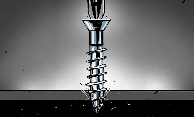
They hold together everything from the most delicate watch to the largest bridge. The world is literally kept from coming apart by screws and bolts, and yet we don’t often give a thought to these mechanisms. Part of that is probably because we’ve gotten so good at making them that they’re seen as cheap commodities, but the physics and engineering behind the screw thread is interesting stuff.
We all likely remember an early science lesson wherein the basic building blocks of all mechanisms laid out. The simple machines are mechanisms that use an applied force to do work, such as the inclined plane, the lever, and the pulley. For instance, an inclined plane, in the form of a splitting wedge, directs the force of blows against its flat face into a chunk of wood, forcing the wood apart.
Screw threads are another simple machine, and can be thought of as a long, gently sloped inclined plane wrapped around a cylinder. Cut a long right triangle out of paper, wrap it around a pencil starting at the big end, and the hypotenuse forms a helical ramp that looks just like a thread. Of course, for a screw thread to do any work, it has to project out more than the thickness of a piece of paper, and the shape of the projection determines the mechanical properties of the screw.
Thread Profiles
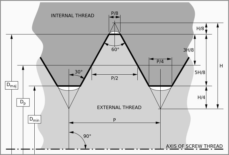
The most common thread profile is the simple V thread, with opposing faces of the thread forming an angle of 60°. This thread angle is a compromise that balances the efficiency, wear rate, strength, and most importantly, the friction of the threads. Along with the pitch, or number of threads per unit length, thread friction contributes to the self-locking, or “non-overhauling” property of most screw threads. Self-locking threads easily convert a rotational force to an axial force, but not the other way around. It’s easy to see this property in action — a nut spins easily on a screw with finger pressure, but push the nut as hard as you can along the long axis of the screw and the screw will not start spinning. Self-locking keeps tools like screw jacks from unwinding under load.
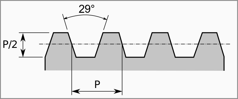
Screw thread profiles can be modified from the standard V profile for better performance under different loads. The Acme profile, a trapezoidal shape with faces forming an included angle of 29° and with large flat crests and roots, is particularly suited to high-load applications like vises and clamps. It’s also found in lead screws such as those used in linear actuators found in everything from DVD players to CNC machines. The Acme profile is also found in the lead screws of most metal lathes because it works well with split nuts. Split nuts are just what they sound like — an internally threaded element that has been split lengthwise and can be opened and closed around a lead screw. This is used to advantage in thread cutting operations, which the split nut closes around the lead screw at the start of thread cutting and opens at the end of the cut, starting and stopping the movement of the cutting tool against the workpiece in repeatable locations.
Cutting and Rolling
For precision threads and low-volume production, cut threads are common. Cut threads are produced in either a lathe or a CNC machine by removing material to form the thread profile, either with a thread cutting tool translated lengthwise against a rotating workpiece, or with a tap (for internal threads) or a die (for external threads).
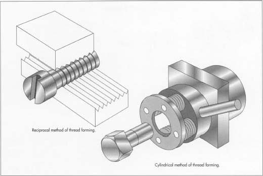
Cutting threads is time-consuming, though, so for mass production, external threads are generally formed with a rolling operation. A forged blank is clamped tightly between a pair of grooved dies, one of which is stationary. The opposing die moves perpendicular to the long axis on the blank, pressing the thread profile into it. Since no material is removed from the blank and because the material is work hardened, rolled threads can be stronger than cut threads. The rolling process is also automation-friendly, and rolling machines can produce thousands of parts per minute.
The internal threads of nuts don’t lend themselves to rolling, so most mass-produced nuts are formed with a hot forging process. Hot slugs of metal are struck by dies that form the head profile and punch the center hole. Later, the cooled blanks are sent to a tapping machine which cuts the internal threads using a tap.
There’s much more to screw threads than this quick tour, of course. The simplicity of screw threads and the ubiquity of threaded fasteners belie the physics behind these mechanisms, but understanding the basics is a great place to start.


Ah, screws, where imperial and metric live together in harmony within the same standards..
Only thing that is not screwed with imperial
Whichever you choose, your still screwed?
Here all day folks!
Whitworth thread: “Hold my beer…”
Ah, screws, made good in Manchester!
they are United
ACME screwed the coyote a number of times.
But he did it 29° off axis.
Let it be noted that the first who coined “screw you” and “nuts to that” took a turn for the worst.
And came undone
And went nut
Somewhere an archaeologists is digging up the very first screw, and nut.
I suffered a Eureka moment when contemplating 3d printing a screw the other week.
All threads are a non concentric circle that linear extrudes with a rotate per layer.
With that in mind, a spreadsheet and Openscad linear extrude makes any thread easy to make.
Very well thought out!
Not actually a circle, but close enough in some cases. See this:
https://www.freecadweb.org/wiki/Thread_for_Screw_Tutorial#Method_4._Sweeping_a_horizontal_profile
Good one, I hadn’t thought about googling it as a circle works fine for everything I have done since but worth readong about.
I use Inventor 2015 with coolOrange thread modeler plugin. Works great
I would have liked to see a little about the history of threaded fasteners – they were once incredibly rare because we hadn’t developed ways to make them in quantity. I’m, of course, meaning after the relative ubiquity of metallurgy but before the screw became what it is today.
Whitworth is far superior. http://www.fastenerdata.co.uk/media/wysiwyg/imagescmspages/unc_threads.jpg
The French??????????????
Backwards compatibility.
“There’s much more to screw threads than this quick tour, of course.”
How true; thank you for saying this up-front.
One “screwy” topic often overlooked is multi-start threads (a.k.a. multiple-start threads, Google the terms).
The Wikipedia “Screw thread” page is good, but briefly touches on this subject of “starts”. Look here under: “Lead, pitch, and starts”:
https://en.wikipedia.org/wiki/Screw_thread
Excerpting from the above Wikipedia link:
“Single-start means that there is only one “ridge” wrapped around the cylinder of the screw’s body. Each time that the screw’s body rotates one turn (360 deg.), it has advanced axially by the width of one ridge. “Double-start” means that there are two “ridges” wrapped around the cylinder of the screw’s body. Each time that the screw’s body rotates one turn (360 deg.), it has advanced axially by the width of two ridges. Another way to express this is that lead and pitch are parametrically related, and the parameter that relates them, the number of starts, very often has a value of 1, in which case their relationship becomes equality. In general, lead is equal to pitch times the number of starts.”
This graphic from the above referenced Wikipedia page helps to explain the concept of “starts” (a two-start example):
https://en.wikipedia.org/wiki/File:Lead_and_pitch.png
One place you commonly encounter multiple start threads is when you screw/unscrew the cap on a high-quality Fountain Pen.
Often a fountain pen cap and barrel will have mating threads that have two or more (often three) starts. Increasing the number of starts preserves the number of threads while decreasing the number of turns it takes screw or unscrew the barrel from the cap (which is more user-friendly).
Preserving the nunber of threads helps to maintain the integrity of the cap-barrel seal against unwanted ink leaks while reducing the number of turns need to screw/unscrew the barrel and cap.
Using rotating machines, it is more complex (costly and time-consuming) to mill multi-start threads, especially the inner-threads found in the cap of a fountain pen. Tooling costs increase significantly if the multi-starts threads are to be milled in one-pass instead of multiple passes, one per thread.
Here’s an example (with pictures) of chasing an EXTERNAL multi-start thread on a lathe:
https://www.ctemag.com/news/articles/cutting-multiple-start-threads
If anyone has an example of the lathe tooling required for multi-start threads in ONE pass, chime in – especially if you have an example of chasing INTERNAL multi-start threads.
Have Fun!… Me
How about the occasional times when the rolling machine messes up and makes a zero-start “screw”? I’m having trouble finding photos, but I’ve seen them in person, and they’re great for a laugh.
They call them car keys.
Tehe
https://www.sandvik.coromant.com/en-gb/knowledge/threading/thread-turning/selection-of-insert/insert-type
bottom of the page, multi-point inserts can be used for multiple start threading both interior and exterior threading. They do require more control over your machining environment but ive seen them used before.
No, it says right on the page the multi-point inserts are so you don’t have to make as many passes.
it was an example and the first result after a 2 second search, i have seen tooling where all the teeth are of equal length of which by selecting the correct feed rate you can use each tooth to cut an individual thread. It is possible, my apologies for not showing the correct insert as i cant seem to find the catalog i saw it on. They tent to be rare and usually used for softer metals as it is not a cost effective tool to make if the wear rate is too high. they tend to work similar to threading mills which have multiple teeth such as:
http://www.iscar.com/eCatalog/Family.aspx?fnum=1398&mapp=TH&app=120&GFSTYP=M
Where with such a mill you are able to set the helical interpolation such that you end up with a multi start point thread. I do remember the turning insert being from a specialty catalog but even so, if you are working with softer metals such as brass it would be possible to make such a tool out of HSS
@Mike
Thanks for the link – interesting. It seems the graphic on the linked page shows an example of a two-start insert tool. It seems the first and second cut tool vees are of different height, perhaps this for the first cut to be of lesser depth where the second cut is deeper to finish. But at the end of the insert tool travel, the first cut will never be completely deep enough. I guess this is OK if the finished mating part has some other means to stop further travel, but is not ideal IMO. I think each cut multi-start thread should end with the same thread depth. Perhaps a better implementation would be an insert cutting tool that has two vees offset by 180 degrees with the first following the second, and by extension a three-start having three vees offset by 120 degrees each following in insert travel one after the other. Hmmm…
you are right in your analysis of that specific insert, that is exactly what it is meant to do. I was only using it as an example as multi point tooling is starting to get into specialty tooling. The example i provided is meant to reduce the number of passes by doing multiple cuts with one tool for a singe start thread but if you check out this milling tool:
http://www.iscar.com/eCatalog/Family.aspx?fnum=1398&mapp=TH&app=120&GFSTYP=M
you can see the idea of what i mean. in the milling tool all of the teeth are of equal depth and you set your helical tool path based on your thread pitch desired. I have seen turning tools with even length teeth but they were in a specialty tool catalog for softer materials.
Thread milling has generally taken over in CNC operations, both in hmcs and vmcs. A CNC lathe with live tooling and the right cam software can churn out internal multi start threads with very little trouble.
The trouble comes in being able to afford one!
Had my first try and making an internal thread on a part with a custom tool on the CNC machine. Now I am wondering why I even bothered had tapping any threads :) although the forming tools are not cheap the finish is perfect every time.
I’m still getting to grips with doing the same on the lathe as that has not been converted to CNC (yet)
Doing threads on a non-CNC lathe is easy. There should be a setting for threading and a little counter so you can start the threads perfectly timed every time. We have a Tormach CNC lathe and it’s awesome for threading by we also have a Grizzly gunsmith lathe what works great for threading as well.
Most common use of multi-start screws is probably jar lids. It significantly reduces the difficulty in locating the lid correctly to start screwing it on.
Double thread screws are made to go in quicker in assembly time. I have had Italian made organs use these in the pedal board holding the spring tension in the metal springs. If they go in easier with more “ramp” they come out by themselves even easier! Junk! In order to save a few seconds we have self disassembly that continually falls apart. We’re screwed.
I gotta be first with this remembrance from Big Bang Theory (episode The Desperation Emanation):
Leonard: What would you be if you were attached to another object by an inclined plane, wrapped helically around an axis?
Sheldon: Screwed.
Leonard: There you go.
Actually, NEVER cut threads. Too costly, (labor) weakens the grain of the base material, (Except perhaps plastic)
And if it’s your life in the car @ 140 mph, the cut bolts will shear with spectacular results. (Film at 11)
on exterior threads i would agree, on interior threads you might have a harder time convincing people. That being said, there are other methods to bring strength back into the part through heat treating or anodizing.
Also if i were to build anything, then i wouldn’t be threading the nuts or bolts at all. Instead i would be buying them based off of bolt grade, the interior threads into billet components would also be designed in such a way that the forces acting upon the bolt are not in an axial direction but in a radial direction. thus putting significantly less stress on the threads of the bolt and instead uses the threads to maintain tightness.
That’s like saying never use aluminum because it will break before an identical steel part.
Just design it properly for the forces you are handling and the materials you are using.
If your bolts are shearing, you’ve designed it wrong, as screws are never supposed to be carrying shearing loads – the parts you clamp down with the bolts are supposed to hold together by the friction of the clamping force.
Hi.
Maybe someone here will be able to help me. I am looking for a formula or on-line calculator or some hint how to calculate the following: I want to attach electric motor to a pair of rods with thread and I want it to lift lower around 100kg in around 1 m range. Distance between rods will be aroound 1-1.5m . Stability will be provided by other means. Problem is: i don’t know how should I choose engine (power) and thread parameters. Any tips?
Here’s a hint: pitch * RPM = speed.
From your travel speed and gravity, you can calculate the potential energy gained in the lift and hence the motor power. Don’t forget friction though as it may dominate unless you use a thread profile that is actually designed for this purpose, and the threads must be properly lubricated.
For example
5mm pitch * 1000rpm = 5000mm/min = 0.083m/s.
100kg * 9.81N/kg * 0.083m/s = 82W.
Actually, the efficiency of the thread will need to be below 50% if you expect the thread to be self-locking. Significantly below 50% for practical purposes.
get a petrol/diesel/jet engine instead of electric, weld it all together by eye
In 1978, my wife and I toured the “Treasures of Tutankhamun” exhibit at the LA County Art Museum.
One of the glass cases contained examples of wooden artifacts taken from the tomb. To my amazement there were some
hand made wood screws looking exactly like modern day wood screws. No, they weren’t accidentally dropped by workers
unpacking the exhibit.
As a non-American I would like to add some info.
Firstly threads have a mesh ratio. This is from the gaps shown in the “V” thread graphic in the top of this article. If you had no gaps then the mesh ration would be 100% and the screw would bind solid.
The size of a screw is the size that would have been 100% mesh so your 1/4 inch screw will fit into a 1/4 inch hole with a small gap.
There are 3 common standards for machine screws.
Metric – A M2.5 screw fits in a 2.5mm hole with the gap mentioned. Some metric screws are available with both a course and fine thread.
British Standard Whitworth (BSW) – A very common standard in the building industry but not common for machinery. Threaded rod is often Whitworth.
Unified Thread Standard (UNC) (UNF) – The “C” in “UNC” is for course thread and the “F” in “UNF” is for fine thread.
This standard has some peculiarities.
THE UNC course standard was created before the UNF fine standard so there are some fine threads in the UNC standard that may catch you out.
The other trap is the numbering system changes. Bolts of 1/4 inch and above are simply numbered by their size ie 1/4 inch bolt.
Bolts below 1/4 inch have a different numbering system like the #4/20 screws in you desktop computer. The first number that is preceded with the “#” symbol is the size expressed by the equivalent sheet metal gauge thickness instead of a fraction of an inch. The second number is the Threads per inch (TPI).
So a #4/20 screw is the size of number 4 gauge sheet metal minus the gap mentioned above and has 20 threads per inch.
I haven’t had to learn anything about UNEF because where I am almost everything is metric especially with fine threads. I wasn’t even aware of UNEF.
Please feel free to elaborate.
A lot of camera gear (both video and still) use UNEF threads for the lenses regardless of their origin…
Nope, number size screws are not the sheet metal gauge in size.
Yes they are but they are not an American standard. They are based on the Swedish standard created by Brown & Sharpe during world war 2 for sheet metal (not to be confused with wire gauges which are different).
Compare these –
B&S Gauges –
On this page – http://www.armstrongmetalcrafts.com/Reference/SheetMetalGaugeWeight.aspx
Or this page = http://www.custompartnet.com/sheet-metal-gauge
UNF Gauges –
On this page – https://en.wikipedia.org/wiki/Unified_Thread_Standard
Sorry, this relates B&S sheet metal gauges to British Association Screws (BA) rather than UNC/F.
Boy does it add a layer of confusion when you start talking about threads on pipes. :)
Pipe down..
Depends on what you call a gun – I think of them as machines. Many barrel threads are Whitworth – including those for the fantastically common German Mauser. You can almost make 60 deg threads fit – with a file by cutting some of the tops off…but this is a case where it’s a lot better to do the correct thing.
When FRICTION isn’t enough.
While the discussion has been about screw design and standards mostly, I feel compelled to mention how I solved a problem with screws. The case screws on a Honda XR-80 I used to own kept coming loose, even with just one ride. I added some silicone RTV to the threads, and they never came out without a screwdriver after that. (I know, Loctite is made for that, but I already had RTV).
The chain had damaged the case in front of it, and would let dirt in to contaminate the points. I used some thin sheet aluminum over the hole, and RTV to hold it there, and didn’t have to replace the points after that. As a kid that was a good thing because the local Honda dealer charged $50 to install a new set of points.
then there’s also Nordlock…
I happen to work in the automotive industry and deal with this kind of issue regularly, using loctite or similar is actually a poor solution as it may just be hiding the problem which could come back to bite you when you least expect it.
When tightening a bolt, you’re converting torque to axial tension, this tension forces the components together, and friction between the components is what’s actually holding everything together. If that tension should drop to zero, the friction between the components also drops to zero, allowing them to move around which could eventually lead to fracture of the bolts or components.
If you apply loctite to a bolt that keeps working loose, all you’ve done is stop it spinning, it may still have lost all it’s tension (this can happen for a number of reasons which I won’t go into…), potentially leading to catastrophic fracture, though bolts can usually take quite a beating before that happens.
More often than not the culprit is either compressible material in the joint (e.g. paint, plastic or dirt) or insufficient torque (which may require a higher grade bolt to improve upon), however there’s many odd reasons. Interestingly, the solutions are often counter intuitive, e.g. going down a bolt size is sometimes the answer!
Suffice it to say, it’s a complicated subject :)
I feel another HaD article coming on. ;-)
The common failures are:
1.Insufficient Clamp Force
The majority of bolted joints rely on the clamp force which is generated by the torquing or tensioning of bolts to sustain the forces which are applied.
The inclusion of a gasket in a joint to prevent leakage is only effective as long as there is sufficient clamp force generated by the bolts to allow effective sealing. With forces applied to the joint, the forces are transmitted by friction as a result of the clamp force generated by the bolts, leading to a secure bolted connection.
2. Thread Stripping
Thread stripping can be a problem in many designs where tapped holes are required in low tensile material. In general terms, thread stripping of both the internal and external threads must be avoided if a reliable design is to be achieved. If the bolt breaks on tightening, it is obvious that a replacement is required.
When a bolt is being tightened, two threads are mated together, which leads to the tightness of the bolt. When the two threads are mated together, a shear stress is applied across the threaded section. If this stress becomes too high, the section will shear. This is known as thread stripping.
Thread stripping internally strips parts of the internal thread itself and becomes embedded around the external thread.
This type of bolt thread stripping is very serious, and must never be allowed to occur. Its occurrence is a certain sign that there is something seriously wrong with the bolts. If it is observed, the bolting procedures must be re-examined and re-evaluated immediately. If it is allowed to persist, serious consequences may result because the bolts will not only sustain a preload, but external loadings may be transmitted directly to the bolts and cause joint failure.
3. Fatigue Failures
Fatigue failures typically occur within a couple of threads, where the bolt engages into the internal thread. Failure is then reached due to the high stress gradient within the region.
Fatigue failures can be particularly hazardous because they often occur with no visible warning signs and the failure is often sudden. Fatigue failures are often unknowingly avoided in gasketed joints simply because the required crush for the gasket often dictates a torque or bolt tension that minimizes the risk of a fatigue failure. However, changing to a new gasket type later on which requires less crush may be the initial cause of bolt fatigue failure.
It is not unusual to assume that a bolt has failed due to overload when it has in fact failed from fatigue, which can also be a consequence of self-loosening.
4. Bolt Overload
Bolt overload is a result of the applied force being sufficiently high causing the bolt to fail due to overload. This is a direct result of the axial force being applied acting upon the bolted joint, which then causes the bolt fractures in the threaded area.
5. Excessive Bearing Stress
Bolts are typically made from high strength steels, which when fully tightened, exert high clamp force onto the joint. The area directly under the bolt head or nut face sustains the high bearing stress.
If a maximum stress limit for the joint material is exceeded, then deformation occurs over a period of time. This leads to the extension being lost in the bolt, resulting in the clamp force subsequently being reduced.
Bolts are considered to transfer force between the connected members, one of the ways bolts transfer force is called bearing.
The bearing method assumes that the bolt contacts the side of a hole and there is a compressive force between the bolt and the side of the hole. The magnitude of this compressive force is limited by the strength of the material to handle this compressive force.
Steel after all, is a Chrystal structure. It has many hackable features for the engineering staff to explore.
And in all this so far, no mention of materials science behind the stock used to manufacture the product. I wouldn’t want to be using a screw made out of metal that could rust on an outdoor deck. The tensile strength of the material is as important as the type of pitch, mesh, etc of the screw itself. No mention of the shear strength or elasticity of the materials. No mention of the corrosion treatment processes. No mention of the varying levels of quality control – hint, I wouldn’t be using cheap china grade screws on my homebuilt experimental aircraft. Aviation grade screws are a whole new world onto itself.
Wait, did you just say, “A cheap Chinese screw”?
China Grade is a thing? ;)
Better check your supplier. There are a lot of chinese fasteners out there, even a TSB.
screw has always been one of my favorite Simple Machines ’cause it was the 7″ with Jawbox and Velocity Girl. DC punk rules. http://www.simplemachines.net/machines.html
Nice write up, but you skipped right past the reason Acme threads exist. The most precise and repeatable thread to drive a load with minimal backlash (as desired on machine leadscrews) is the square thread. You’ll see square threads on all early 20th-century American machine tool leadscrews. However, square threads are very difficult to make, because the cutting tool has no relief area; the sides of the tool will bind up as the thread gets deeper. Acme was created as a compromise. It provides just enough angle to give cutting tool clearance during manufacture, while still mostly retaining the desirable properties of a square thread for driving a load.
It may be a good alternative to try the “v” angled thread files. The angle is 60 degrees so it is similar to the angle on Inch, Metric, Pipe, Male, and Female Threads. The files are basically round and they work great in restoring internal and external threads.