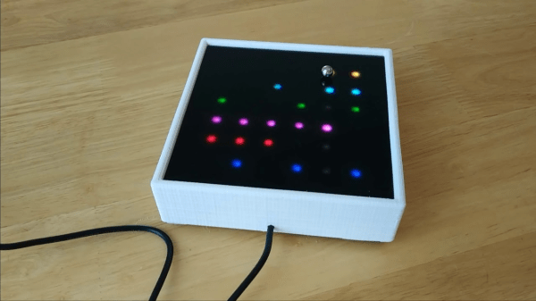
Some hacks just tickle the brain in a very particular way. They’re, for a change, not overly engineered; they’re just elegant, anachronistic, and full of mischief. That’s exactly what [Frans] pulls off with A Gentleman’s Orrery, a tiny, simple clockwork solar system. Composed of shiny brass and the poise of 18th-century craftsmanship, it hides a modern secret: there’s barely any clockwork inside. You can build it yourself.
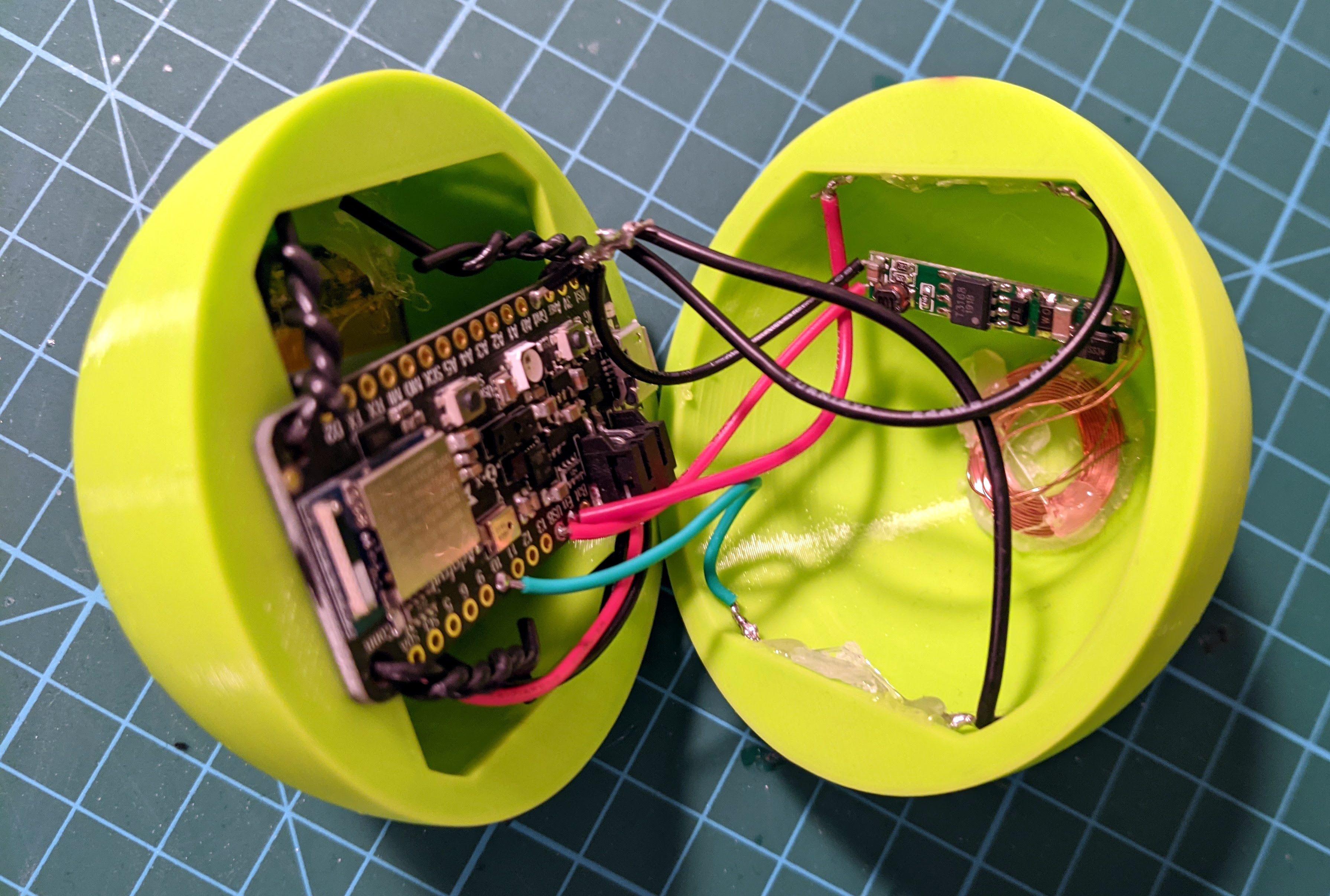
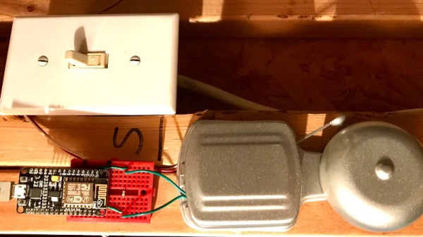
 Peek behind the polished face and you’ll find a mechanical sleight of hand. This isn’t your grandfather’s gear-laden planetarium. Instead of that, it operates on a pared-down system that relies on a stepper motor, driving planetary movement through a 0.8 mm axle nested inside a 1 mm brass tube. That micro-mechanical coupling, aided by a couple of bevel gears, manages to rotate the Moon just right, including its orientation. Most of the movement relies on clever design, not gear cascades. The real wizardry happens under the hood: a 3D-printed chassis cradles an ESP32-C6, a TTP223 capacitive touch module, STSPIN220 driver, and even a reed switch with magnetic charging.
You can even swap out the brass for a stone shell where the full moon acts as the touch control. It’s tactile, it’s poetic, and therefore, a nice hack for a weekend project. To build it yourself, read [Frans]’ Instructable.
Continue reading “Planetary Poetry With A Tiny Digital Core”