At Hackaday, we really appreciate it when new projects build on projects we’ve featured in the past. It’s great to be able to track back and see what inspires people to pick up someone else’s work and bring it to the next level or take it down a totally new path.
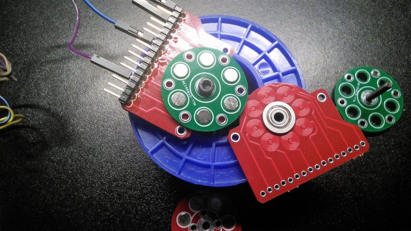
This PCB brushless motor is a great example of the soft collaboration that makes the Hackaday community so powerful. [bobricius] says he was inspired by this tiny PCB BLDC when he came up with his design. His write-up is still sparse at this point, but it looks like his motor is going to be used to drive a small robot. As with his inspiration, this motor has the stator coils etched right into the base PCB. But there are some significant improvements, like increasing the stator coil count from six to eight, as well as increasing the overall size of the motor. [bobricius] has also done away with the 3D-printed rotor of the original, opting to fabricate his rotor from stacked PCBs with cutouts for 5-mm neodymium magnets. We like the idea of using the same material throughout the motor, and it also raises the potential for stacking a second stator on the other side of the rotor, which might help mechanically and electrically. Even still, the prototype seems to hold its own in the video below.
This is [bobricius]’ second entry in the 2018 Hackaday Prize so far, after his not-a-Nixie tube display. Have you entered anything yet? Get to it! Prizes, achievements, and glory await.


Cool. I wonder, if they considered building an induction motor without permanent magnets?
Most don’t have any, which is the basis of their design
Totally doable by using coils excited by small BJTs or Mosfets driven by Hall sensors. they should be wired so that the detection of the reach of a position would switch off power to the corresponding coil and turn on the one in immediate vicinity according to the desired direction.
Those coils should be made of more turns of real wire though so that their inductance can be increased; I believe this motor even though working doesn’t have a good efficiency.
Sensors? There are no sensors in induction motors. There are only coils on both stator (driven) and rotor (closed). I expect it is doable and I wonder how efficient it would be.
On VFD induction motors there is a speed sensor which is needed to set the torque accurately
Or a stepper for an instrument dial
Might work. What are they using for the sensors?
Sensors? Its a stepper motor, not what is commonly referred to as a BLDC. BLCD does not require sensors for some applications either.
They dont require external sensor but they do use back emf to tell what is going on with the motor.
Ususally they do one of those, but BLDC is actually a permanent magnet synchronous motor, you can drive that blindly and assume the rotor follows the signal. This method obviously has its limitations.
Looks like he found a good use for a fidget spinner bearing.
Yes. That is impressive :)
Since most fidget spinner bearings seem to be 608s, some might say that skateboarding is a good use of such bearings and has been for some time
Only for values of good tending towards the minimum :)
Floppy drives used to have that kind of printed motors and “fridge” type magnets.
Can you show one example? I took apart a few (slim type too) but have never seen this solution. I only saw bare coils glued to the pcb, but that’s different.
I’ve seen that as well. A long time ago I was taking apart a dead floppy, hoping to salvage steppers, and was confused a long time ago, until I figured out that it was very similar to this. (This looks far nicer.) It was a 3.5 that used PCB traces for it. I wish I’d kept it now, but it was purged a few moves ago.
Ooooooooh!
Another step towards a home-fabable Nema17!!
It’s a little deceiving to call this a brushless motor in the title. Maybe I’m just being pedantic, but this is really a stepper motor. The title isn’t wrong, but I think most of us probably expected to see the kind of brushless motor that you’d find in a quadrocopter.
It’s still a very cool project! Once we can make a PCB stepper with more torque, RepRaps may be able to do something interesting with the concept.
No, it is a brushless motor, just a two phase brushless motor. They are kind of rare, some high speed spindles use them and some turbo pumps.
What makes a stepper motor a stepper motor is the design of the rotor and stator with the teeth that causes it to move one step per pulse.
Lucian: no deception a all. Every brushless DC motor is a stepper motor. Both steppers and BLDCs come in different numbers of phases – I’ve seen many floppy drive steppers with three-phase drive – so even that isn’t a distinguishing characteristic. The main difference between the two is that a stepper usually has a whole lot more poles. But also, stepper motors have the same number of stator poles as rotor poles, while BLDCs use different numbers. Note that the example shown uses eight stator and six rotor poles. So this is closer to most BLDC motors than it is to most steppers. So you’re not just being pedantic, you’re also being wrong.
Furthermore, in what way do you think this couldn’t do the work of a quadcopter motor? If your tripping point is that it uses two-phase drive, and therefore couldn’t be used with a a hobby electronic speed controller, what part of the principles demonstrated do you think wouldn’t translate trivially to three phase? I’m guessing that the maker wanted to save a little money on the drivers, since two-phase requires only two H-bridges, while three-phase requires three.
I’d like to see these turned into inexpensive galvanometers for cheap stereo lithography 3D printers.
That’s not going to happen. Two totally different beasts.
Wonder how well this could work as a generator.. oh snap did I just spoil the punch?
Not as well as a traditional motor. The magnetics of this are lacking. You can get pancake motors just as thin as his that would be way more efficient.
The coils remind me of this recent image: https://www.jpl.nasa.gov/spaceimages/details.php?id=PIA22335
Looks like someone thought of this two years ago. A PCB motor train sethttps://youtu.be/ri6LIGlWdx4?t=175 Found It today.
This would make a nice cooling hat for a raspberry pi after glueing/3D printing some fins.
They could sandwich stators and rotor PCBs now…
I’m not sure that would be the best thing, mechanically. A single thick rotor or stator is much stronger than a number of thinner rotors and stators totaling the same thickness.
They could also complete the magnetic circuit by using ferrous plates on the exposed sides of the stator and the rotor (or the stack of stators and rotors). This would reduce the reluctance greatly, with a corresponding increase in torque.
Another way to do this is with a Halbach array in place of the simple arrangement of magnets in the rotor (see https://en.wikipedia.org/wiki/Halbach_array and https://hackaday.com/2017/05/08/powerful-professional-brushless-motor-from-3d-printed-parts/), which confines the magnetic field to within the motor using magnets instead of iron.
This still leaves the PCB as a high-reluctance element in the magnetic circuit, but the whole point of a pancake motor is that by making the coils very thin but covering a large area, the reluctance of a coil can be kept low without incorporating a magnetic core.
Just another application of the same priciple :)
https://www.youtube.com/watch?v=ri6LIGlWdx4
I’m not sure what sort of audience this is aimed at, eight year olds perhaps?
I turned the sound off after about 20~30 seconds but that only made it worse. By the time it got to showing off the pcb (1:51), I simply couldn’t stomach any more.
Which is rather unfortunate as it looks like a very good piece of engineering from what I did see.
This and [Carl Bugeja] work is a very cool idea, love to see how this pans out :)
At least we now know how sonic screwdrivers get their sound!