Emulating A Complete Commodore 64

When the Commodore 64 was released in 1982, it was a masterpiece of engineering. It had capabilities far outstripping other home computers, and that was all due to two fancy chips inside the C64. The VIC-II, the video chip for the C64, had sprites and scrolling, all stuffed into a single bit of silicon. The SID chip was a complete synthesizer on a chip. These bits of silicon made the C64 the best selling computer of all time, but have also stymied efforts to emulate a complete C64 system on a microcontroller.

[Frank Bösing] has just managed to emulate an entire C64 on a Teensy 3.6. The Teensy uses an exceptionally powerful microcontroller, but this is a labor of love and code.

The inspiration for this project comes from a reverse-engineered SID chip that was ported to the Teensy 3.2. The SID chip is the make it or break it feature of any C64 emulation, but the Teensy 3.2 didn’t have enough RAM for the most recent versions of reSID. With the release of the Teensy 3.6, [Frank] figured the increased amount of RAM would allow a complete C64 system, so he built it.

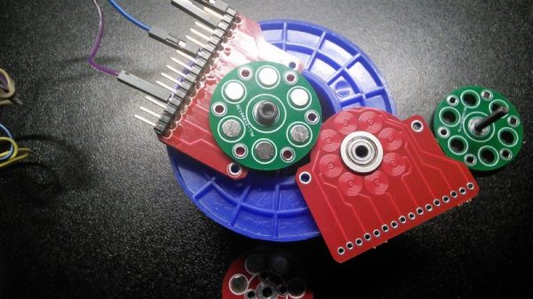
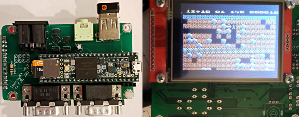
The new C64 emulator uses a Teensy 3.6, with a small add-on ‘shield’ (or whetever we’re calling them) to provide connectors for joysticks and the Commodore IEC bus. There’s audio out, support for USB keyboards, and support for an IL9341 SPI display or a regular ‘ol VGA display.

The entire development of this Commodore emulator has been documented over on the PJRC forums, and all the code is over on GitHub. It’s a fantastic piece of work, and as the video (below) shows, this is a real Commodore 64 that fits in your pocket.

Continue reading “Emulating A Complete Commodore 64”

Improved camera slider controls

Improving Controls For A Camera Slider Kit

We’ve all gone through it. You buy a kit or even an assembled consumer item, and it’s either not quite right or it’s only a part of what you need. Either you do a fix, or you add to it. In [Jeremy S. Cook’s] case, he’d been working for a while with a camera slider kit which came with just the slider. He’d added a motor and limit switches but turning it on/off and reversing direction were still done by manipulating alligator clips. Now he’s put together some far better, and more professional-looking controls.

He started by replacing the DC motor with a servo motor modified for continuous rotation. Then he built a circuit around an Arduino Nano for controlling the motor and put it all in a carefully made box which he bolted to the side of the slider. A switch built into the box turns it on and off, and a potentiometer sets the direction of the slider. While not necessarily new, we do like when we see different approaches being taken, and in this case, he’s using magnets to not only hold the case’s cover on for easy access, but also a couple of them to hold the 9-volt battery in place. Check out his construction process and the new slider in action in the video below.

Continue reading “Improving Controls For A Camera Slider Kit”

An LED Effect For Every Occasion

Quality software development examples can be hard to come by. Sure, it’s easy to pop over to Google and find a <code> block with all the right keywords, but having everything correctly explained can be hit or miss. And the more niche the subject, the thinner the forum posts get. Bucking the downward trend [HansLuijten] provides an astoundingly thorough set of LED strip patterns in his comprehensive post titled Arduino LED strip effects.

Don’t let the unassuming title lead you astray from the content, because what’s on offer goes beyond your average beginner tutorial on how to setup a strand of NeoPixels. [HansLuijten] is thorough to a fault; providing examples for everything from simple single color fades and classic Cylon eyes to effects that look like meteors falling from the sky. Seriously! Check out the videos on their webpage. Those chasing lights you see around theater signs? Check. Color twinkle and sparkle? Check. Color wipes and rainbow fades? Check, and check. Continue reading “An LED Effect For Every Occasion”

Evolution Of The ESP8266 Party Button

Sometimes the best part of building something is getting to rebuild it again a little farther down the line. Don’t tell anyone, but sometimes when we start a project we don’t even know where the end is going to be. It’s a starting point, not an end destination. Who wants to do something once when you could do it twice? Maybe even three times for good measure?

Original version of the Party Button

That’s what happened when [Ryan] decided to build a wireless “party button” for his kids. Tied into his Home Assistant automation system, a smack of the button plays music throughout the house and starts changing the colors on his Philips Hue lights. His initial version worked well enough, but in the video after the break, he walks through the evolution of this one-off gadget into a general purpose IoT interface he can use for other projects.

The general idea is pretty simple, the big physical button on the top of the device resets the internal ESP8266, which is programmed to connect to his home WiFi and send a signal to his MQTT server. In the earlier versions of the button there was quite a bit of support electronics to handle converting the momentary action of the button to a “hard” power control for the ESP8266. But as the design progressed, [Ryan] realized he could put the ESP8266 to deep sleep after it sends the signal, and just use the switch to trigger a reset on the chip.

Additional improvements in the newer version of the button include switching from alkaline AA batteries to a rechargeable lithium-ion pack, and even switching over to a bare ESP8266 rather than the NodeMCU development board he was using for the first iteration.

For another take on MQTT home automation with the ESP8266, check out this automatic garage door control system. If the idea of triggering a party at the push of a button has your imagination going, we’ve seen some elaborate versions of that idea as well.

Continue reading “Evolution Of The ESP8266 Party Button”

A Brushless Motor On A PCB, Made From PCB

At Hackaday, we really appreciate it when new projects build on projects we’ve featured in the past. It’s great to be able to track back and see what inspires people to pick up someone else’s work and bring it to the next level or take it down a totally new path.

This PCB brushless motor is a great example of the soft collaboration that makes the Hackaday community so powerful. [bobricius] says he was inspired by this tiny PCB BLDC when he came up with his design. His write-up is still sparse at this point, but it looks like his motor is going to be used to drive a small robot. As with his inspiration, this motor has the stator coils etched right into the base PCB. But there are some significant improvements, like increasing the stator coil count from six to eight, as well as increasing the overall size of the motor. [bobricius] has also done away with the 3D-printed rotor of the original, opting to fabricate his rotor from stacked PCBs with cutouts for 5-mm neodymium magnets. We like the idea of using the same material throughout the motor, and it also raises the potential for stacking a second stator on the other side of the rotor, which might help mechanically and electrically. Even still, the prototype seems to hold its own in the video below.

This is [bobricius]’ second entry in the 2018 Hackaday Prize so far, after his not-a-Nixie tube display. Have you entered anything yet? Get to it! Prizes, achievements, and glory await.

Continue reading “A Brushless Motor On A PCB, Made From PCB”

Storm Detector Modules: Dancing In The Rain

Earlier, we had covered setting up an AS3935 lightning detector module. This detector picks up radio emissions, then analyzes them to determine if they are a lightning strike or some other radio source. After collecting some data, it outputs the estimated distance to the incoming storm front.

But that only gets you halfway there. The device detects many non-lightning events, and the bare circuit board is lacking in pizzazz. Today I fix that by digging into the detector’s datasheet, and taking a quick trip to the dollar store buy a suitable housing. The result? A plastic plant that dances when it’s going to rain!
Continue reading “Storm Detector Modules: Dancing In The Rain”

Friday Hack Chat: Simulating Analog

Simulation is a valuable tool for any hardware developer. Instead of building hardware for a long debugging session, you can emulate a microcontroller and blink your lights with some Javascript. Instead of working on a Bluetooth protocol for your fitness wearable, you can just whip up some Javascript and get it working that way. Once all your Javascript is in order, then you can finally move over to hardware. It saves development time, and it saves money.

But this is all digital. What do you do if you’re working on an analog system? Lucky for you, there’s a system built for analog and mixed-signal analysis, and it’s been around for decades. This week we’re talking all about PSpice, a simulator for analog analysis that will give you voltages and currents across every node in a schematic.

For this week’s Hack Chat, we’re going to be talking about PSpice with [Abha Jain] and [Alok Tripathi]. [Abha] has worked at Cadence for 19 years and has been part of the PSpice R&D team for the last decade. She’s an MTech in VLSI Design Tools and Technology and holds multiple EDA patents. [Alok] graduated in 1993 with a B. Tech in Electrical Engineering. He started working at the Department of Atomic Energy in 1993 as a power supply and control system designer for particle accelerators. Currently, he’s working with Cadence and is the Product Engineering Architect for PSpice and OrCAD.

For this Hack Chat, we’re going to be discussing the challenges of system-level simulation, improving reliability, yield, and productivity of circuit design, the issues of Spice simulation, and answer the question, ‘on an infinite grid of one Ohm resistors, what is the resistance between two nodes a knight’s move apart?’ You are, of course, encouraged to add your own questions to the Hack Chat. You can do that by leaving the questions as a comment on this Hack Chat’s event page.

join-hack-chat

Our Hack Chats are live community events on the Hackaday.io Hack Chat group messaging. This week it’s going down at an unusual time: 8 AM Pacific, Friday, March 30th  Want to know what time this is happening in your neck of the woods? Have a countdown timer!

Click that speech bubble to the right, and you’ll be taken directly to the Hack Chat group on Hackaday.io.

You don’t have to wait until Friday; join whenever you want and you can see what the community is talking about.