An electromagnetic coil gun takes a line of electromagnets working together to form a moving electromagnetic field. These fields accelerate a project and boom, you have electricity moving matter, often at an impressive rate of speed.
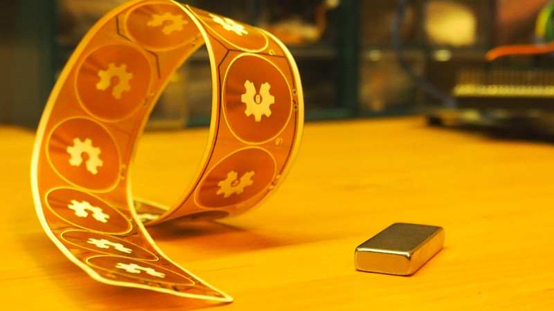
[Carl Bugeja] has taken the idea and in a sense turned it upon its head with his flexible PCB actuator. Now the line of electromagnets are the moving part and the magnetic object the stationary one. There is still a line of flat PCB inductors in the classic coil gun configuration, but as the title suggests on a flexible substrate.
The result is a curiously organic motion reminiscent of some lizards, caterpillars, or snakes. It can move over the magnet in a loop, or flex in the air above it. It’s a novel moving part, and he’s treated us to a video which we’ve placed below the break.
He has plans to put it to use in some form of robot, though while it certainly has promise we’d be interested to know both what force it can produce and whether flexible PCB is robust enough for repeated operation. We salute him for taking a simple idea and so effectively proving the concept.
We’ve brought you [Carl]’s work before, most notably with his PCB motor.


“These fields accelerate a project and boom”. So it lobs a failed build out the window at supersonic speeds? Certainly a worthwhile endeavor…
That explains why a few half-finished PCB with French text ended up in my backyard. Someone in Quebec got upset with mistakes and blasted it all the way to Michigan.
“…an impressive rate of speed.”
Is that English for “high acceleration”?
And instead of “power” you can say “an impressive time of energy.”
Don’t you mean “an impressive energy per time?”. An “impressive time of energy” sounds more like something you would measure in Joule-seconds, not Watts (damned if I know what you’d use Joule-seconds for).
I’ve noticed Jenny’s articles tend to be written at a lower level than most everyone else’s here, avoiding big words like ‘acceleration’ for more dumbed down words like ‘impressive speed’ and such.
Acceleration and speed are not the same. Acceleration is how quickly inertia can be broken and how quickly top speed can be reached. But impressive speed could have horrible acceleration but could reach impressive speeds. Power has more to do with acceleration and less to do with top speed. Speed is controlled by aerodynamics, wheel size, drag, balance, and other contributors. You could hook a Boeing 747 engine to a hotwheels car, but the car can only go so fast, without a track or guidance, before it loses control.
Stop polluting the comment section about lingvistics, I am here to discuss hardware hacks not hacks made on the English language…
What would the benefit be of the flex PCB vs the rigid? Guess it could work as some kind of fin, but moving anything other then the PCB it self would require attaching the PCB to a body. Sure you can attach it to an uneven body but how would that “align/connect” with the “pully/thingie that moves”?
I apologize to Jenny and the other HaD editors for my question on a curious turn of phrase getting turned into a series of attacks from other commenters (especially the appropriately-deleted ones).
I appreciate how hard writing well really is, and I commend the HaD writers in general for collecting, presenting and curating decent quality material. Keep the thick skin, and noli illegitimi carborundum.
Hi Carl. I guess you are quite excited on electromagnetism. :-) Some time ago I have seen an interesting clip about magnetically actuated micro robots. Your experiments remembered me that, and try to find again. Now I have found an even more complete presentation of the same equipments. The basics are obvious, but it seems to me I remember a discussion and calculation and maybe independent hacker experiments on the net about currents in underlying PCB network needed to achieve the similar movements (seen in the below cited clip). The results was depressing. I could not find this hacker investigation in talk eather. Maybe it is on the Hackaday portal :-). Anyway, some trick must be in the solution demonstrated in the clip, to do it with reasonable low currents. It is also interesting, how the passive robots can be actuated independently on the same table. Then and now I have an attempt to dig out more detailed explanation of the principles, but could not find any relevant additional info. (Maybe DARPA strictly keeps the idea? Or I am just not clever enough to find the related sources.) I am curious can you create a similar effect based on your experience. I would be glat to read the ideas, possible better search results, or see some similar “toys” of the members of hacker community too.
Megnetically actuated micro-robots: https://www.youtube.com/watch?v=uL6e3co4Qqc
… imo it is really interesting and thought provoking.
I was wondering – If the energy was harvested from the movement of the flexible pcb, how closely would it match the energy required to create the movement?
I want to know how much this cost to make, and what sort of dimensions that you used. I think this has wonderful potential for applications as a braille display for the visually impaired.
In braille, characters are displayed as raised/lowered patterns of six (6) dot combinations, with an additional two dots for comma/space/cursor position in modern refreshable braille displays (modern refreshable braille display used by computers is 8 dots total).
The standard for braille characters is as follows
a) Each dot is 0.057″/ 1.44mm in diameter, and raised 0.019″/0.48mm in height
b) Distance between adjacent dots in the same braille cell (vertically/horizontally) is 0.092″/2.340mm
c) Distance between dots in adjacent cells is 0.245″ (6.2mm)
(Reference http://www.brailleauthority.org/sizespacingofbraille/sizespacingofbraille.pdf)
So a braille character on a refreshable display is 8 dots (2 x 4) and takes up
H = 1.44mm/2 + (3*2.34mm) + 1.44mm/2 = 8.46mm = 0.333″
W = 1.44mm/2 + (1* 2.34mm) + 1.44mm/s = 3.78mm = 0.149″
space between characters = 6.2mm – 3.78mm = 2.42mm = 0.095″
If you can make the little coils fit within the dimensions of 1.44mm x 1.44mm, and flex/flap up by 0.48mm/0.019″ minimum, then I bet this could be made into a really low cost braille display. Even if it does not feel the exact same way as a conventional braille display I bet GOOD ENOUGH could be acheived for a fraction of the current prices.
From what I understand the current technology uses levered piezo actuators to raise/lower the dots (Assembling this must be like putting together a mechanical wristwatch). This is why a bare-bones 16 character display may cost 1000$, while an 80 character single row display may cost 10 000$ (20″ long display, 8 dots/character). (Ex: a Humanware “Braillenote touch 18″ with 18 characters can cost 4995.00$) I also imagine that a piezo actuated device must also be expensive to assemble and maintain, and must chomp through batteries very quickly.
If you can make a flex board where the coils are on little flaps (like those on a check valve or the flapper on your toilet), and you can get a long-wearing substrate (ex: a typical 250-300 page book has 400 000 Characters, so 100 000 000 characters is the equivalent of 250 average books, Even if you get something capable of 10 000 000 actuations/flexings that can be produced for only a few hundred dollars apiece, this would represent a major cost savings in braille display technology.
Even if the dots flex when you press them, the fact that you could vibrate them would make for a good tactile interface.
for each dot. If I calculate this correctly, the flaps would be a size of 1.44mm x 1.44mm with a max potential kerf/cutout between coils/flaps of 2.34mm – 1.4mm = 0.96mm.
You layer a flat/hard plastic layer beneath the pcb so the flaps do not go below level, and have the magnets arranged in strips beneath the characters (ex: Magnet4Less sells 1/8″ x 3/8″ x 3/8” N45 magnet item #NB012 for 0.36$/magnet or 0.36$ per character). You might even layer up several characters over the same magnet to make a 4-row display, but start with one row of 18 characters).
It would even be able to save on battery life if you had low cost distance/reflectance sensors (such as an ON semiconductor QRE1113GR reflectance/distance sensor) or a capacitative touch sensor set up to detect when fingers were near the characters.
Could you please let me know the dimensions that you are using, what the cost was, what the substrate is, and what the cost would be if you were using a 4 layer pcb?
Thank you.
That isn’t a good application for this design. Too little force, too small space. The force of a solenoid is proportional to the current and the number of windings, this would have few windings, low current plus inefficiencies due to the planar coil.
Traditional coils would provide more force and when mass-producing wouldn’t be too expensive to make – “just” have to make a good winding machine.