How many of you plan to build a wind-powered generator in the next year? Okay, both of you can put your hands down. Even if you don’t want to wind your coils manually, learning about the principles in an electric generator might spark your interest. There is a lot of math to engineering a commercial model, but if we approach a simple version by looking at the components one at a time, it’s much easier to understand.
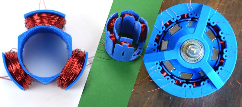
For this adventure, [K&J Magnetics] start by dissect a commercial generator. They picked a simple version that might serve a campsite well, so there is no transmission or blade angle apparatus to complicate things. It’s the parts you’d expect, a rotor and a stator, one with permanent magnets and the other with coils of wire.
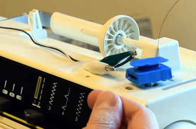
 The fun of this project is copying the components found in the commercial hardware and varying the windings and coil count to see how it affects performance. If you have ever wound magnet wire around a nail to make an electromagnet, you know it is tedious work so check out their 3D printed coil holder with an embedded magnet to trigger a winding count and a socket to fit on a sewing machine bobbin winder. If you are going to make a bunch of coils, this is going to save headaches and wrist tendons.
They use an iterative process to demonstrate the effect of multiple coils on a generator. The first test run uses just three coils but doesn’t generate much power at all, even when spun by an electric drill. Six windings do better, but a dozen finally does the trick, even when turning the generator by hand. We don’t know about their use of cheap silicone diodes though, that seems like unintentional hobbling, but we digress.
Making turbine blades doesn’t have to be a sore chore either, and PVC may be the ticket there, you may also consider the vertical axis wind turbine which is safer at patio level. Now, you folks building generators, remember to tip us off!


Traditional DIY wind turbine generator, at least in my country, starts its life as one or three electric motors from old washing machines. Both stators and rotors are stripped. With more than one motor, the stators are assembled into single one, new rotor is created, and covered with rare earth magnets.Then new winding is made. Everything is assembled and tested. There is no need for iterative design – someone already figured out best ways to generate power and created equations to calculate every parameter of generator…
Would love to hear more about that
Links or it didn´t happen !!!
Here you go:
https://www.elektroda.pl/rtvforum/topic277125.html
https://www.elektroda.pl/rtvforum/topic1209212.html
There are plenty of photos of small wind turbines and generators in these topics, some equations, scans of books and other stuff too. Have fun exploring.
A bit of handy information:
So called “amerykanka”(in Polish) or “american” is a generator made of disks, where at least one holds magnets and one holds coils. It’s like flat BLDC motor. Lacks iron cores for coils which makes it low efficiency. But some people think it’s much more efficient for some mystical reasons…
The other kind is sometimes called “pralkowiec” from polish word “pralka”, which means washing machine…
>”Lacks iron cores for coils which makes it low efficiency. ”
It can’t make it low efficiency – ironless generators are actually higher in efficiency because they get no eddy currents – but the lack of core iron means it needs to spin really fast to make voltage because the magnetic flux density is poor.
You could say it’s low “efficiency” in terms of utilizing the magnets, but for converting motion to electricity it’s actually slightly better – as long as you get the turbine tip speed matched to the generator load. That can be harder to optimize because the generator needs to spin faster than is optimal for most turbine types.
The more technical term is an axial flux generator. They too can include core irons, and you can construct them by laminating pieces of old hacksaw blades into the coils to make an iron core, to make the load curve steeper.
What makes a generator load curve steeper is
1) higher flux density through the copper (stronger magnets)
2) smaller air gaps
The main fault with the “american” generator as it is usually made is, people wind the coils thick and loose, and waste a lot of space so the magnetic field has to jump across a gapof many centimeters – worse still if the magnets are only on one side, because then the coil can repel the field entirely and the generator load goes flat. Instead of increasing the load with speed, it stops making more power and the turbine starts to overspeed.
You’re right, of course. I meant that “american” generator is less efficient at given RPM than washing machine generator. DIY wind turbines usually don’t include gear boxes. So to make this generator useful one would have to make multiple coil and magnet disks into a stack the size of classic washing machine generator. Which would take much more copper and magnets. Washing machine generator is simpler…
There are ways to make the “american” generator perform better than the washing machine motor, and save some copper while you’re doing so, but it’s not immediately obvious.
For example, you can form the copper coils as a single continuous wire going around the disc in a shape similar to the teeth of a gear (intertwining to make three phases). This saves copper, space, and reduces resistance compared to forming individual coils. To increase the voltage then, you use narrower magnets and fit more of them around the disc, and likewise make the “teeth” of the coil narrower to match.
The wheel barrel one is priceless.
Magnetic permeability of plastic is pretty awful. As cool as 3D printing is, you really need to make your rotor and stator out of iron or steel for any sort of efficiency – preferably electrical steel, which is designed for anything electromagnetic.
can I make a lathe and mill with a 3d printer? that’d be awesome.
Yes. Yes you can.
https://hackaday.com/2012/05/21/3d-printing-a-mini-lathe/
https://hackaday.com/2016/01/25/sub-300-cnc-if-you-have-a-3d-printer/
It’s actually more efficient if your motor/generator doesn’t contain any iron, because iron saturates, it forms eddy currents, it has hysteresis losses with changing magnetic fields etc. etc.
But without iron the flux density remains low, so you only get a small voltage per RPM per coil turn, and then you need more copper, which leads to higher resistance, which leads to lower efficiency.
See what we can do with magnetic liquid.
https://www.livescience.com/66018-permanently-magnetic-liquids.html
You can use iron-filled PLA from Protoplasta. Of course, its relative permeability is just like 7 or something, much better than the ~1 of regular PLA, but far less than the ~100 of iron. There’s also thevirtualfoundry.com’s high carbon iron filament that should get you to almost 40 (without sintering). And there’s an advantage to using plastic-bound metal powder: it effectively eliminates eddy currents due to the extremely low electrical conductivity, enabling low loss high speed operation. I’d recommend annealing it first to increase the operational temperature, though.
lol, I haven’t seen a calculator hacked to be a counter since the 90s. Even then, it was by reading a electronics magazine from the late 70s.
in the video @ 1:20 the voice over says: “in each of the 12 coils, we made about 230 turns”.
“About”? When you have a precission counter mechanism, it should be exact, shouldn’t it? Well if you look closely at the counter you’ll see that the counts aren’t counted perfectly. The calculator counter trick works great, but you do need to get your debouncing straight. So a reed relais isn’t the way to go, but I understand why they chose to use it here.
But despite that, fun project, a project that’s certainly not perfect the first time… motors and generators are great learning project for students.
I didn’t knew that there are magnets out there with a little notch, that’s useful info that might come in handy some day, so thanks for the tip.
“How many of you plan to build a wind-powered generator in the next year?”
Soon as one gets enough wind to make it worth the trouble.
I generate my own wind!
And everyone in the room has harnessed it. :)
I did something very similar a few years ago with a hamster wheel. I glued alternating magnets to the outside of the plastic wheel, and mounted a series of coils next to it. I used it to power a tiny LED Christmas tree on top of the cage.
It was for my daughter’s Chinese dwarf hamster, and I wish I could find some of the pictures.
BTW: A Chinese dwarf hamster is good for a max of 40ma for short periods, but can generate 20ma continuously.
I’m not saying that this is definitely worth an article, but it is probably something I would write.
I’ll see if I can dig up the CAD files and photos.
40ma at what voltage? (Power matters)
Probably just enough to light a couple LEDs in parallel, so about 2.3 Volts? 100 mW?
Exactly. Initially I use a rectifier and powered 2. Then I removed the rectifier and flipped one of them so they would alternate. It looked better for the Christmas tree to have the flashing lights! Anymore than that and the hamster would get tired and not run as long on the wheel.
It’s posts like this that make me wish hackaday had a “like” button!
God no!
And then there’s that clever “claw” design for the inner part (be it the rotor, e.g. in car dynamos [1] or the stator, e.g. in bicycle hub dynamos [2]. There you replace the multiple permanent magnets or multiple coils (coil is always better where the stator is, for obvious reasons ;-) by one fat magnet/coil oriented axially and with claw-shaped poles shepherding the magnetic field. Pics help, so here [3] are some nice ones.
[1] https://en.wikipedia.org/wiki/File:Dynamo.JPG
[2] https://en.wikipedia.org/wiki/Magneto#Bicycles
[3] https://www.jmag-international.com/catalog/25_ClawPoleAlternator_Capacitance/
Cheap steppers use this configuration often, because it can be made of sheet metal in a few steps. It has disadvantages.
40ma at what voltage or total power?
No Javascript = reply fail. sorry, please delete this
I recall winding slot car motors a few decades ago.
Still have some armature wire.
Feeling cute, might wind a generator or two. IDK.
“cheap silicone diodes” are squeezed out of caulk gun? Silicon probably works better!
[ ] works with 3d printed plastic claws
[x] demonstrates that you need iron for a serious generator
The sewing machine winder and articles on those alone are worth the article. The wind turbine is just extra fluff… ok… that’s interesting also. Do I see another 3D printer filament in the making for optimal 3D printed turbines or updates in the sintering and compression or whatever the method?
Very nice project.
I have a question, is there a mathematical formula to calculate the size of the coil, number of turnings and wire thickness if I know the power and the size of the magnet?
.